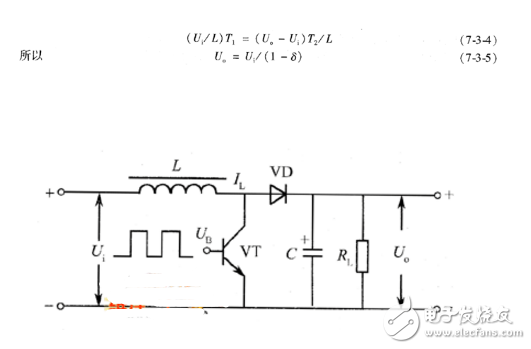
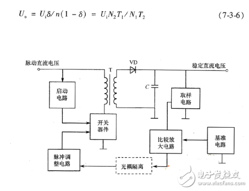
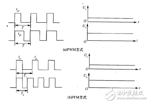
Series, Parallel and Transformer Coupling (Parallel) Switching Power Supply According to the connection mode of the switch tube and the load, the switching power supply can be divided into three types: series type, parallel type and transformer coupling (parallel type). Tandem type . The basic form of the switching power supply shown in FIG. 1 is a series switching power supply, which is characterized in that the switching adjustment tube VT is connected in series with the load R1. Therefore, the switching tube and the freewheeling diode have lower withstand voltage requirements. Moreover, the filter capacitor has current when the switch tube is turned on and off, so the filter performance is good, and the ripple coefficient of the output voltage å° is small; the cross-sectional area of ​​the core of the energy storage inductor is required to be small. The disadvantage is that there is no isolation transformer between the output DC voltage and the grid voltage, so-called "hot chassis", which is not safe enough; if the switch tube is internally short-circuited, all input voltages are directly applied to the load, which may cause overload or over-current of the load. , damaged components. Therefore, the output terminal generally needs to be protected by a voltage regulator. Figure 1 Basic circuit and working waveform of switching power supply Parallel type . The basic circuit of the shunt type switching regulator power supply is shown in Figure 2. The working waveform is basically the same as the series circuit. Because the switching tube VT is connected in parallel with the load RL, it is called parallel type. In addition, diode YD is commonly referred to as a pulse rectifier and C is a filter capacitor. When the base of the switch tube inputs the switch control pulse, the switch tube is periodically turned on and off. When the switch tube is saturated and turned on, the input voltage Ui is applied across the energy storage inductor L. At this time, the current in the inductor rises linearly, the diode VD is turned off and the inductor L stores energy. At this time, the current required for the load RL is supplied by the voltage charged on the capacitor for a while. When the switch is turned off, VD is turned on, the current through the inductor decreases linearly, and the induced voltage is left negative right positive. The input voltage Ui and the induced voltage on the inductor L are connected in series with the same polarity, and the power input Ui and the inductor L are released. The energy simultaneously supplies current to the load RL and charges the capacitor C. Similarly, when the dynamic balance is reached, the amount of current (energy) that the inductor L increases when the switch is saturated is equal to the amount of current (energy) that is reduced when the switch is turned off, that is, the energy on the inductor remains constant, so Figure 2 Basic circuit of parallel switching power supply It can be seen that the parallel type switching regulator power supply can also stabilize or adjust the output voltage by controlling δ. At the same time, it can be seen that since δ<1, the parallel type switching power supply belongs to the step-up type power supply, and the maximum reverse of the switch tube The voltage Uce max = Uo (> Ui). The series switching power supply shown in Figure 1 is a step-down power supply, and the maximum reverse voltage Uce max=Ui that the switching tube is subjected to. Pulse transformer coupling (parallel) type . The basic circuit of the transformer coupling (parallel) type switching power supply (self-excited) is shown in Figure 3. The switching device can be a bipolar transistor or a FET, T is a switching (pulse) transformer, VD is a pulse rectifier diode, C is a filter capacitor, and RL is a load. Here, the primary winding of the pulse transformer acts as a storage inductor, and the pulse transformer transmits energy through inductive coupling, so that the input end and the regulated output end are isolated from each other, so that the casing (floor) is not charged, and at the same time, it is convenient to obtain more The DC voltage is convenient for production and maintenance. Therefore, most color TVs use a transformer-coupled switching power supply. If the pulse transformer is regarded as an ideal transformer with an initial and secondary turns ratio of n:1, the secondary parameter is equivalent to the primary, and can be drawn into the parallel type circuit form shown in Figure 2, except that nUo is used instead of Figure 2. Uo. For the circuit of Figure 3, available Figure 3 Basic circuit of transformer-coupled switching power supply Since n>1, the transformer type switching power supply is generally a buck output. The maximum pulse voltage that the switch tube is subjected to in the switching power supply is Uce max=Ui+nUo. Switching power supplies generally have three modes of operation : frequency, pulse width fixed mode, fixed frequency, variable pulse width mode, frequency, pulse width variable mode. The former working mode is mostly used for DC/AC inverter power supply or DC/DC voltage conversion; the latter two working modes are mostly used for switching regulated power supply. In addition, the switching power supply output voltage also has three working modes: direct output voltage mode, average output voltage mode, and amplitude output voltage mode. Similarly, the former mode of operation is mostly used for DC/AC inverter power supply, or DC/DC voltage conversion; the latter two modes of operation are mostly used for switching power supply. Switching power supply can be divided into two major categories: AC/DC and DC/DC. The DC/DC converter has been modularized, and the design technology and production process have been matured and standardized at home and abroad. The modularization of AC/DC is due to Its own characteristics make it difficult to encounter technical and process manufacturing problems in the process of modularization. (1) DC/DC conversion The DC/DC conversion converts a fixed DC voltage into a variable DC voltage, also known as DC chopping. There are two ways to operate the chopper. One is that the pulse width modulation mode Ts is unchanged, the ton is changed, and the other is the frequency modulation mode. The ton is unchanged and the Ts is changed (prone to interference). Its specific circuit consists of the following categories: A, Buck circuit - step-down chopper, its output average voltage U0 is smaller than the input voltage Ui, the same polarity. B. Boost circuit——Boost chopper, whose output average voltage U0 is greater than the input voltage Ui, and the polarity is the same. C, Buck-Boost circuit - buck or boost chopper, whose output average voltage U0 is greater or less than the input voltage Ui, the opposite polarity, the inductance transmission. D, Cuk circuit - buck or boost chopper, its output average voltage U0 is greater than or less than the input voltage Ui, the opposite polarity, the capacitance is transmitted. Today's soft switching technology makes a qualitative leap in DC/DC. The various ECI soft-switching DC/DC converters designed and manufactured by VICOR in the United States have a maximum output power of 300W, 600W, 800W, etc., and the corresponding power density is (6.2). , 10, 17) W / cm3, the efficiency is (80 ~ 90)%. Japan's NemicLambda company recently introduced a high-frequency switching power supply module RM series using soft switching technology, its switching frequency is (200 ~ 300) kHz, power density has reached 27W / cm3, using synchronous rectifier (MOS? FET instead of SCHOTT The base diode) increases the overall circuit efficiency to 90%. (2) AC/DC conversion AC/DC conversion is to convert AC to DC, and its power flow direction can be bidirectional. The power flow from the power supply to the load is called “rectificationâ€, and the power flow is returned to the power supply by the load called “active inverterâ€. AC/DC converter input is 50/60Hz AC, because it must be rectified and filtered, so the relatively large size of the filter capacitor is essential, and at the same time due to safety standards (such as UL, CCEE, etc.) and EMC directives Restrictions (such as IEC, FCC, CSA), EMC input must be added to the AC input side and components that comply with safety standards are used, which limits the miniaturization of the AC/DC power supply. In addition, due to internal high frequency, high voltage, and large The current switching action makes it more difficult to solve the EMC electromagnetic compatibility problem, which puts high requirements on the internal high-density installation circuit design. For the same reason, the high voltage and high current switch increase the power supply operation loss, which limits the limitation. The modularization process of AC/DC converters must use the power system optimization design method to achieve a certain degree of satisfaction in working efficiency. AC/DC conversion can be divided into half-wave circuits and full-wave circuits according to the wiring mode of the circuit. According to the number of power phases can be divided into single phase, three phase, multi phase. According to the working quadrant of the circuit, it can be divided into one quadrant, two quadrants, three quadrants and four quadrants. The advantages of transformer-coupled (parallel) type switching power supply are: 1 by indirect sampling by adding a secondary winding or by using an optocoupler to achieve power isolation, so that the main power circuit is isolated from the AC grid, so-called "cold chassis" circuit; If the switch is internally short-circuited, it will not cause overvoltage or over-current of the load; 3 Allow the auxiliary power supply load to be independent of the main power load. That is, without the main power load, the auxiliary power can still be obtained from the main power. The disadvantages are: 1 pair of switch tubes and freewheeling diodes have high withstand voltage requirements; 2 output voltage ripple coefficient is high; 3 requires large energy storage inductance. Self-excited and other excitation switching power supply According to the excitation mode of the switching device, it can be divided into self-excited and other switching power supplies. The self-excited switching power supply does not need to have a special oscillation circuit, and the switch adjustment tube also serves as the oscillation tube. It is only necessary to set a positive feedback circuit to make the circuit start to work, so the circuit is relatively simple. His excitation switching power supply requires a special oscillator and a starting circuit, and the circuit structure is relatively complicated. Pulse width modulation and pulse frequency modulation switching power supply The output of the switching regulator power supply is related to the on-time of the switching transistor, which is determined by the duty cycle δ of the switching pulse. The voltage regulation control is realized by modulating the duty cycle of the switching pulse, and the control mode is pulse width modulation ( PWM) and pulse frequency modulation (PFM). The pulse width control (width adjustment) type switching power supply voltage stabilizing circuit does not change the operating frequency of the switching tube during the process of stabilizing the output voltage by changing the switching pulse width (controlling the switching tube conduction time). In the process of voltage regulation control, the pulse frequency control (frequency modulation) type switching power supply changes the duty cycle of the switching pulse, and the operating frequency of the switching tube also changes with it, so it is called a frequency modulation-width adjustment type power supply. The modulation waveforms of the PWM mode and the PFM mode are respectively shown in Figures 4(a) and (b), tp represents the pulse width (i.e., the on-time tON of the power switch tube), and T represents the period, from which it is easy to see the difference. But they also have in common: 1 Both use the time ratio control (TRC) voltage regulation principle, regardless of changing tp or T, the final adjustment is the pulse duty cycle. Although the methods used are different, the control objectives are the same, which can be said to be the same. 2 When the load changes from light to heavy, or the input voltage changes from high to low, the output voltage is kept stable by increasing the pulse width and increasing the frequency. Figure 4 Modulation waveforms of two control modes Mixed modulation The hybrid modulation method refers to a method in which the pulse width and the switching frequency are not fixed and can change each other, and it belongs to a hybrid mode of PWM and PFM. Since both p and r can be individually adjusted, the duty cycle can be adjusted to the widest range, making it suitable for switching power supplies for laboratory use and wide range adjustment. Typical working mode of the switch According to the connection and working mode of the switch tube, the switching power supply can be divided into four types: single-ended, push-pull, half-bridge and full-bridge. The single-ended type uses only one switching transistor, the push-pull or half-bridge uses two switching transistors, and the full-bridge uses four switching transistors. At present, switching power supplies such as color TV sets, displays, printers, and fax machines are often single-ended, while the microcomputer switching power supplies are all half-bridge type. Ral7035 Control Box,Q235 Control Box,304Ss Control Box,316Ss Control Box Nantong Double Star Automation Equipment Co., Ltd. , https://www.nt-doublestar.com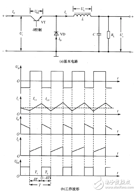
How to classify switching power supplies? What are the basic types of switching power supplies?
How to classify switching power supplies?