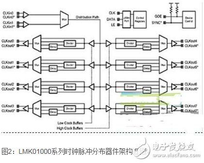
There is no end to the need to improve the healthcare environment, so higher resolution medical imaging equipment is needed to better observe the human condition. High resolution brings problems with signal acquisition and transmission. Based on the above requirements, a stable low jitter clock is needed to improve signal acquisition accuracy and improve signal transmission within the system. In this article, we will discuss the clock distribution system for large imaging devices, which is a challenge for design engineers. In the mid and late 1970s, computerized X-ray axial stratified angiography (CAT) scanning has emerged in the medical world. Improvements in computer processing power and information acquisition time have greatly improved the scanning speed of the device, the content of the information, and the clarity of the image. Today, our scanners combine positron emission tomography (PET) with magnetic resonance imaging (MRI) or X-ray computed tomography to provide better information recording and better picture quality. This is a dual mode scan and is one of the latest designs. Clock, noise and image resolution In particular, PET scanners require a radionuclide tracer that produces positrons when these radionuclides decay. When positrons lose potential energy, they are combined with electrons in different ways, by which a gamma ray of 511 keV emitted almost in the opposite direction will be produced. In order to record the response lines or chords of two gamma ray photons as they pass through the patient's body, a detection loop is required. The diameter of the detection ring must be able to accommodate the passage of the patient's body, which takes about 1 meter and has 500 to 1000 channels on the detection ring. The detector must be able to correlate the two gamma ray events from the positron to the electronic annihilation process to a line of response, not as a random event. In addition, these channels must accurately measure the energy of the gamma ray to detect errors caused by Compton scattering, which can cause errors in the location of the source. There are several ways to achieve the above objectives, but all require an accurate clock signal to match the detection window. It is very easy to generate a precise and stable high frequency clock, but how to distribute the clock signal in a large diameter detection loop is a challenge because the fast clock edge will be lost due to the transmission medium. Some detectors use the fiber to transmit the output of the scintillation crystal to a channel plate with optoelectronic components (PMT or APD). Such a layout makes the distance of the detection electronics smaller, but the clock distribution is still affected by damage, offset, vibration, and other degradation problems on the channel, which ultimately affect the image noise and the resolution that needs to be achieved. Clock distribution In CT imaging and other similar data acquisition systems, the clock limits the performance and data conversion effects of those time-based systems. In order to keep the high speed clock clean, the signals are distributed in differential form such as LVPECL or LVDS. Because they are transmitted on the channel board, the distribution of the clock pulse is affected when the drive load (such as a large FPGA) and the adjustment board layout are skewed, that is, the arrival time of the edge pulse is affected. To solve this problem, semiconductor vendors have created clock distribution devices that allow engineers to "solve" skew problems by programmable delays and re-driving clock signals. Figure 2 shows a block diagram of National's LMK01000 series of clock pulse distribution devices that not only control calibration skew, but also control programmable dividers, multiplexers, and output drivers. This is critical to the in-system programmable performance of managing clocks and reducing timing errors. When transmitting clock pulses through the channel board, twisted pair or dual coaxial cable is required, but new problems will follow. Because the distance of high-speed signal transmission is near or far, these signals will suffer from high-frequency attenuation, group delay and other distortion caused by crosstalk and system noise, especially when high-voltage electric drive PMT is required. In most cases, clock recovery is accomplished by retiming the phase-locked loop (PLL) device. For example, the LMK03200 precision zero-delay clock regulator is used, which includes a high-frequency phase-locked loop, an integrated VCO, and some features of the LMX01000. Summary of this article Large data acquisition systems such as PET, CT, MRI, and dual-mode scanners require tight control of the clock to minimize image distortion, system noise, and overall system performance. New products with greater light output and faster decay times make possible TOF detection on PET scanners. This latest technology requires a higher frequency clock to produce higher definition images. With the development of new technologies, the future of CT scanning will become brighter, but as the resolution of detected images continues to increase, the timing rate will further increase, so clock distribution will be a challenge that designers need to deal with for a long time. Best Tire Inflator For Trucks,Truck Tire Pump,Air Pump For Truck Tires,Portable Truck Tire Inflator SHENZHEN SMARTNEWO TECHNOLOGY CO,. LTD , https://www.newopump.com