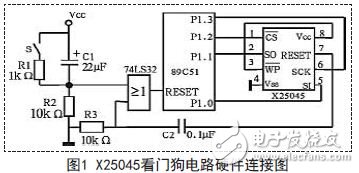
With the increasing application of single-chip microcomputers in important fields such as national defense, finance, and industrial control, the reliability of single-chip application systems has become an important topic of concern. The reliability of single-chip application system is determined by many factors, which are roughly divided into hardware system reliability design and software system reliability design. First, hardware system reliability design (1) Selective design In the system hardware design and processing, you should use good quality connectors to design the process structure; select qualified components for rigorous testing, screening and aging; technical parameters (such as load) must be left in the design. Use components in quantities or deratings; improve the quality of printed boards and assemblies. (2) Redundancy and fault-tolerant design It is impossible to ensure that the MCU application system is 100% fault free. Fault tolerance means that when a certain component of the system fails, the system can still work normally, that is, the ability to tolerate faults is added to the system. In order to make the system fault-tolerant, appropriate redundant units must be added to the system to ensure that when a component fails, the redundant component can take over its work, and the original component can be restored to its pre-error state. Hardware redundancy can be designed at the component level, subsystem or system level. For example, a two-machine system is used at the system level, and the two systems are mutually standby. (3) Adopt hardware anti-interference measures The electromagnetic interference signal generated from the power supply system and through the wire transmission, electromagnetic coupling, etc., is an important factor in the unstable operation of the single chip system, and effective interference suppression measures must be taken in the system hardware design. In the single-chip application system, the system monitoring circuit is often used to detect errors or malfunctions of the system, automatically alarming or automatically returning the system to normal working state. If the power failure monitoring, watchdog timer, etc. use the 89C51 microcontroller and X25045 watchdog circuit, X25045 hardware connection diagram as shown. The X25045 chip contains a watchdog timer that allows the system to monitor the system's monitoring time. If there is no bus activity during the preset time of the watchdog timer, the X25045 will output a high level signal from RESET, and output a positive pulse through the differential circuits C2 and R3 to reset the CPU. In the circuit shown in Figure 1, there are three reset signals of the CPU: power-on reset (C1, R2), manual reset (S, R1, R2), and Watchdog reset (C2, R3), which are added by OR gate synthesis. RESET terminal. The time constants of C2 and R3 do not have to be too large, and there are hundreds of microseconds, because the oscillator of the CPU is already working. The timing of the watchdog circuit can be determined by the cycle time of the specific application, usually slightly longer than the maximum cycle time during normal operation of the system. When programming, you can add a dog feed instruction in the appropriate place of the software, so that the watchdog's timing time will never reach the preset time, and the system will not reset and work normally. When the system runs away and cannot be captured back by software traps or other methods, the watchdog timing time quickly increases to the preset time, forcing the system to reset. It should be noted that when the program is running normally, a dog feeding instruction should be added in the appropriate place to make the timing of the normal operation of the system less than the preset time. The system will not reset. Second, software reliability design The software and hardware of the microcontroller application system are closely related. In order to make the whole system have high reliability, in addition to improving hardware reliability as much as possible, software reliability design is also essential, and software reliability must be solved from design, test and long-term use. The anti-interference ability of the single-chip system is an important indicator of system reliability. Since the instruction system of the 51 single-chip microcomputer is a complex instruction set structure, its anti-interference performance is low, especially in the case of industrial control, and it can not work normally without adding additional anti-interference measures. The main purpose of the anti-interference design of the MCU software is to find the "running" program in time, and pull the program into the normal track in time. The main methods are: instruction redundancy, software "trap", software "watchdog" and so on. (1) Instruction redundancy The CPU fetching process takes the opcode first and then the operand. Manual insertion of some single-byte instructions at a critical point in the program, or rewriting a valid single-byte instruction is called instruction redundancy, usually by inserting more than two bytes of NOP after a two-byte instruction and a three-byte instruction. instruction. This allows even the fly-away program to fly to the two-byte instruction and the three-byte instruction operand. Due to the existence of the narrow operation instruction NOP, the subsequent instructions are prevented from being erroneously executed, and the program is ready to be put on the right track. In addition, instructions that play an important role in system flow, such as RET, RETI, LCALI., LJMP, JC, etc., can insert two NOP instructions after these instructions, which can put the running program on the track to ensure the execution of these important instructions. . Instruction redundancy can only cause the CPU to no longer execute the operand as an opcode, but can not actively reverse the wrong execution direction of the program. To correct the wrong execution direction of the program, the following techniques are required. (2) Design software "trap" Usually, the unused EPROM space in the program memory is filled with the narrow operation instruction NOP, and finally a jump instruction is filled in, jump to the runaway processing program, or directly fill in the instruction LJMP 0000H, when the runaway program falls into this area. . You can go to the right track after performing a blank operation. If the unused EPROM space is large, you can fill in a few empty operation instructions and jump instructions evenly. The structure of several empty operation instructions plus a jump instruction is called "software trap". The general structure of a software trap is: NOP NOP LJMP FLY FLY is a runaway processing subroutine. If the program is executed normally, the software trap part will never be executed. Only when the program runs into the trap, the software trap will immediately jump the program to the normal track. Even if the program does not fly into the trap, you can encounter a software trap after the program performs a wrong operation, and then get back on track. In addition to the blank area of ​​the program memory, the software table should also set the software trap at the end of the data table. If the data table is large, software traps should be set in the middle of the data table to ensure that the program can fly to the data area and get back on track. In addition, if the program memory is large enough, you can set a software trap between every two subroutines. When the interrupt used is open due to interference, a software trap is set in the corresponding interrupt service routine to capture the interrupted error in time. The number of software traps should be determined according to the actual interference situation and the capacity of the program memory. If too few can not perform effective run-to-fly interception, if too much, it will take up a lot of program memory space. (3) Software "watchdog" technology The running program is after some wrong operation. Often enter the "infinite loop", which is often said to "crash." Usually, the "software watchdog" technology is used to get the program out of the "infinite loop". The principle of the software "watchdog" technology is to continuously detect the program cycle running time. If the program cycle time is found to exceed the maximum cycle running time, the system is considered to be trapped. "Infinite loop" requires error handling. In practical applications, the timing interrupt service routine is usually used to periodically check the operation of the main program. For example, select one byte in the RAM area as the software watchdog register, and the main program increments the register once every cycle. The interrupt service routine of the timer TO decrements the register and checks it once every time, if the program is executed normally. . The watchdog register does not change or change very little. If the watchdog register changes or changes greatly, the system is stuck in an "infinite loop." Need to handle the error. In industrial applications, severe interference sometimes destroys the interrupt mode control word, turns off the interrupt, and causes the watchdog to fail. In this case, a ring interrupt monitoring system can be used. The timer T is monitored by the timer TO, the program is monitored by the timer T1, and the main program monitors the timer T0. The software "watchdog" with this ring structure has good anti-interference performance and greatly improves system reliability. For the measurement and control system that needs to use the Tl timer for serial communication frequently, the timer Tl cannot be interrupted, and can be monitored by the serial port interrupt. Of course, the maximum cycle of the main program, the timer T0 and the Tl timing cycle should be considered in a reasonable manner. Software "watchdog" technology requires the use of timers, and in most control programs, timers are a tight resource. This limits the practical application of the "software watchdog" technology. We can take some technical treatments to multiplex the software "watchdog" program with the other timers to complete the timing function. Complete the function of the software "watchdog". (4) Check the RAM area flag data and find serious interference in time This method is to select several fixed units in the RAM area and set them to fixed data in the initialization program. The contents of these units will not change as long as the program runs normally. If the data of any of these RAM cells changes due to the program "running" or other interference, the microcontroller system has been seriously interfered and cannot be reliably operated. We can check the contents of these RAM cells in a timely manner during the execution of the program. Once the data changes are found, the LJMP 0000 H statement is executed immediately to force the microcontroller to reset. (5) Refresh the output port Excluding serious interference, when the MCU system is seriously interfered, the state of the output port may also change due to interference. During the execution of the program, the output port is refreshed according to the operation result of the relevant program module, and the state of the output port can be eliminated. The effect is to correct the wrong output status in time. (6) Perform multiple input sampling Avoid serious interference, strong interference will affect the input signal of the single-chip microcomputer, causing errors or misreading of the instantaneous sampling of the input signal. To avoid the influence of interference, it is usually adopted by repeated sampling and weighted average method. Third, the conclusion The reliability of the operation of the single-chip system will be disturbed by uncertain factors. To improve the reliability of the MCU application system, we must start with software and hardware. To improve the system's own defense behavior, the above mentioned methods to improve reliability are not used alone. Only by combining these methods effectively according to the actual situation can we achieve the best anti-interference effect and make our single-chip system Work reliably and reliably.
Electric dc motors were the
first type widely used, since they could be powered from existing
direct-current lighting power distribution systems. A electric Dc Motor's speed can be controlled over a wide range, using either a variable supply
voltage or by changing the strength of current in its field windings. Small electric dc motor are used in tools, toys, and appliances. The universal motor
can operate on direct current but is a lightweight motor used for portable
power tools and appliances. Larger electric dc motor are used
in propulsion of electric vehicles, elevator and hoists, or in drives for steel
rolling mills.
Areas of application: the Electric Dc Motor rotor part of the armature iron core, armature, commutator, such as equipment, electric dc motor is suitable for most electronic products, such as electric screwdriver, laser, smart home, gas valve, etc
Applications:
Method of use: the best stable in
horizontal plane, installed on theelectric dc motor output
shaft parts, cannot use a hammer to knock, knock prone to press into the electric
dc motor drive, may cause damage to internal components, and cannot be
used in the case of blocked.
Operating
temperature range:
Electric dc motor should be used at a temperature of -10~60℃.
The figures stated
in the catalog specifications are based on use at ordinary room
temperature catalog specifications re based on use at ordinary room
temperature (approximately20~25℃.
If a electric dc motor is used outside the prescribed temperature range,the grease on the gearhead
area will become unable to function normally and the motor will become unable
to start.Depending on the temperature conditions ,it may be possible to deal
with them by changing the grease of the motor's parts.Please feel free to
consult with us about this.
Storage
temperature range:
Electric dc motor should be stored ta a temperature of -15~65℃.
In case of storage
outside this range,the grease on the gearhead area will become unable to
function normally and the motor will become unable to start.
Service life:
The longevity of
geared motors is greatly affected by the load conditions , the mode of
operation,the environment of use ,etc.Therefore,it is necessary to check the
conditions under which the product will actually be used .The following
conditions will have a negative effect on longevity.Please consult with us
should any of them apply.
â—Use with a load
that exceeds the rated torque
â—Frequent starting
â—Momentary reversals
of turning direction
â—Impact loads
â—Long-term
continuous operation
â—Forced turning
using the output shaft
â—Use in which the
permitted overhang load or the permitted thrust load is exceeded
â—A pulse drive
,e.g.,a short break,counter electromotive force,PWM control
â—Use of a voltage
that is nonstandard as regards the rated voltage
â—Use outside the
prescribed temperature or relative-humidity range,or in a special environment.
â—Please consult with
us about these or any other conditions of use that may apply,so that we can be
sure that you select the most appropriate model.
when it come to
volume production,we're a major player as well .each month,we rurn out
600000 units,all of which are compliant with the rohs directive.Have any
questions or special needed, please contact us, we have the engineer group and
best sales department to service to you Looking forward to your inquiry. Welcome
to our factory.
Electric Dc Motor Electric Dc Motor,Mini Electric Motor,12V Electric Motor,Electric Motor Gearbox Shenzhen Shunchang Motor Co., LTD. , https://www.scgearmotor.com