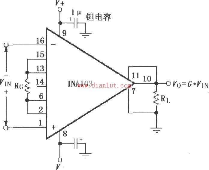
The following is the circuit diagram of the Application Connection Circuit of INA103.
As shown in the figure, the power supply terminal of the chip should be filtered using a 1μF tantalum capacitor and placed as close as possible to the power supply pin of the chip. This helps reduce noise and improve stability. The output detection terminal (pin 11) and the output reference terminal (pin 7) must be connected with low resistance. Even a small resistance in the connection path can significantly reduce the amplifier's common-mode rejection ratio, which may lead to signal distortion or instability.
To avoid self-excitation of the amplifier, all leads should be kept as short as possible. Additionally, the gain-setting resistors and the gain-detection components should be directly connected to the chip’s pins to minimize parasitic effects. Proper layout and routing are crucial for optimal performance.
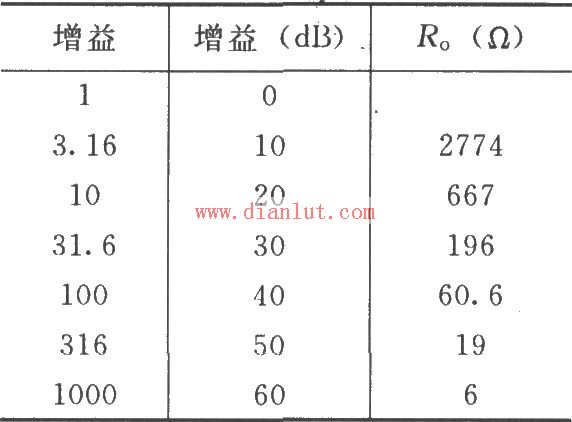
The choice of gain is shown in the table below.
Electric Lifting Column,Electric Cylinder Linear Actuator,Telescopic Linear Actuator,Electric Slide Actuator Kunshan Zeitech Mechanical & Electrical Technology Co., Ltd , https://www.zeithe.com

 (Editor: Circuit Diagram)