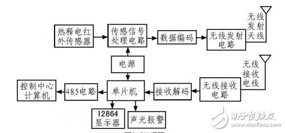
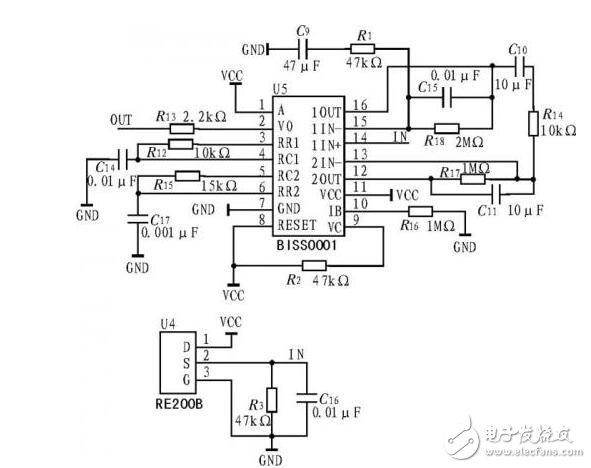
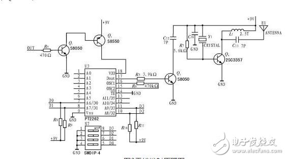
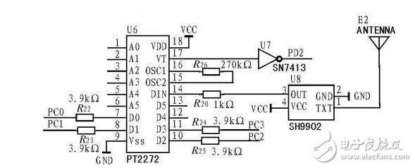
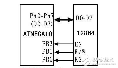
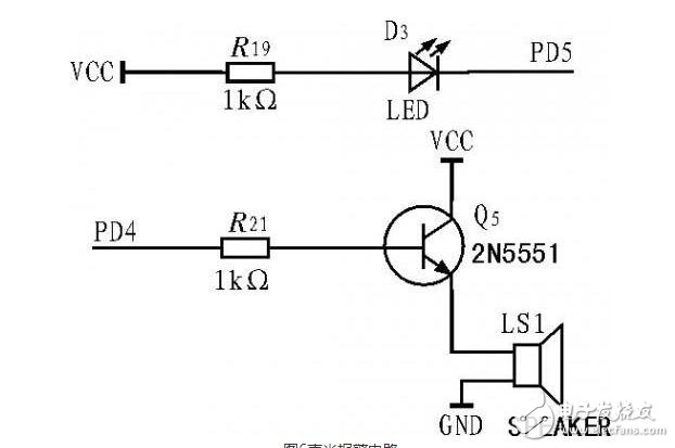
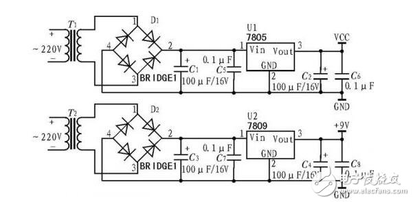
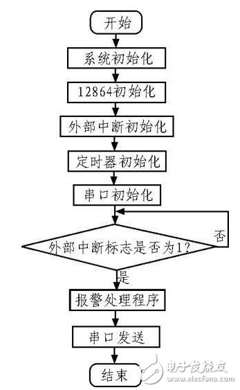
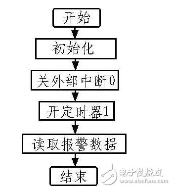
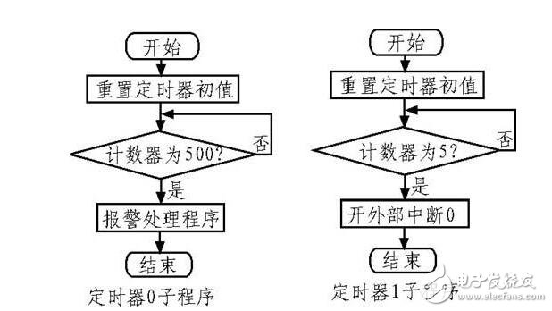
The principle of infrared detectors, which are divided into two types: The infrared detector is a kind of radiant energy converter, which is mainly used to convert the received infrared radiation energy into other forms of energy such as electric energy, heat energy and the like which are convenient for measurement or observation. According to the energy conversion method, infrared detectors can be divided into two categories: heat detectors and photon detectors. The working mechanism of the heat detector is based on the thermal effect of the incident radiation, which causes the change of a certain electrical characteristic of the detector. The photon detector is based on the photoelectric effect generated by the interaction of the incident photon flux and the detecting material, which is manifested by the detector response element free loading. The change in the number of carriers (ie, electrons and/or holes). Since this change is caused by a change in the number of incident photons, the response of the photon detector is proportional to the number of photons absorbed. The response of the heat detector is proportional to the energy absorbed. The heat transfer process of the heat detector includes: thermal resistance effect, thermal volt effect, thermo-pneumatic effect and pyroelectric effect. The photon detector's transduction process includes: photovoltaic effect, photoconductivity effect, photoelectromagnetic effect and light emission effect. Here we use the principle of pyroelectric infrared detection to make this security system. In order to realize wireless automatic alarm and monitoring for major safety places, according to the basic principle of pyroelectric infrared sensing, an infrared detector for receiving mobile body radiation is designed and realized. The detector is controlled by ATmega16 microcontroller. The wireless communication technology and signal detection technology communicate with the controller through the wireless transceiver module. The controller is connected to the control computer through RS-485, and the whole system forms a wireless network to realize multi-channel wireless sound and light alarm and remote monitoring. In addition, the system also designed a display module to facilitate data reading and analysis. The design has the advantages of strong real-time performance, high reliability, low cost and convenient maintenance. With the rapid development and wide application of electronic technology and microcomputer technology, it provides modern home security and garage. The alarm system of major safe places such as offices, banks, museums, etc. has brought about new changes and a new look. In daily life, various wireless detection systems are born, which greatly saves the cost of laying dedicated communication circuits and facilitates the planning of various safe places. Alarming through wireless communication is an extremely convenient and effective means, and related application promotion. As part of a communication system, wireless communication consists of a signal source and a receiver, a transmitting device, a transmission medium, and a receiving device. The transmitting device of the wireless digital communication system is divided into two parts: source coding and source decoding. The receiving device of the wireless digital communication device performs demodulation, decoding, decryption, etc., that is, completes the function of inverse transformation of the transmitting device, and the purpose thereof is to correctly recover the original signal from the signal with interference, and at the same time, the multiplexed signal can be Release, achieve the correct way. The wireless communication-based security system uses various wireless communication technologies to construct basic system functions for control technology, as well as modular, structured, and functional technologies. The system is easy to maintain and improve. According to the infrared detection principle, the infrared detection sensor can be divided into two types: photon detector and heat detector. A photon detector is a radiation detector made by an external photoelectric effect or an internal photoelectric effect, also called a photoelectric detector. The principle is that the electrons in the detector absorb the energy of the photons, causing changes in the state of motion to generate electrical signals, which are commonly used to detect infrared radiation and visible light. The pyroelectric infrared detector is a pyroelectric type infrared sensor based on the principle of thermoelectric effect, and the internal thermoelectric element is composed of a high-thermal coefficient iron-titanium-lead-mercury ceramic and a filter lens window of aluminum cholate and triethylene sulphate. Polarization changes with temperature. The pyroelectric infrared detector is composed of a sensing probe element, an interference filter and a FET matching device. As the collector of the security system, the sensor adopts the common interface as the output interface of the signal, which is very suitable for the signal input of various sensors. After the signal is output, an integrated switch is used. When the signal reaches the preset value, the integrated switch is turned on to make the coded transmitting module work, thereby encoding and modulating the transmitted signal. First, we must understand its system principle: The security system device is an acousto-optic alarm device based on pyroelectric infrared detection principle, which wirelessly transmits and receives signals, including data acquisition, data coding, wireless transceiver, single chip control, signal detection, etc., by ATmega16 controller and pyroelectric release. The electric infrared sensor, the coding chip PT2262, the decoding chip PT2272, the liquid crystal display 12864 and the like are composed. The main content of this system research is to detect the alarm signal through the pyroelectric infrared sensor. When there is a signal, the wireless transmitting module is started to encode the signal and then transmitted to the ATmega16 MCU. After receiving the signal through the wireless receiving module, the received encoded data is input to the system. On the decoder, the encoder output terminal drives the AVR microcontroller to generate an external interrupt. The ATmega16 MCU collects the data output from the decoder into the internal MCU to realize the sound and light alarm and judge the alarm number. The data is displayed on the LCD and transmitted to the control center. computer. Second, our team system circuit makes a design: The system hardware circuit includes a wireless transmitting system, a wireless receiving system, and a power supply circuit. The wireless receiving system is controlled by an ATmega16 single-chip microcomputer, and the peripheral device is mainly composed of a wireless receiving module, a receiving and decoding, an audible and visual alarm circuit, and a display module. The system block diagram is shown in the figure. 1, wireless transmission circuit: The security system collects alarm signals through the pyroelectric infrared sensor principle for encoding and wireless transmission. The signal collected by the sensor is relatively weak and needs to be processed. The processing circuit selects the integrated pyroelectric infrared processing chip BISS0001, which has higher processing signal performance, and is controlled by the op amp, voltage comparator, state controller, and delay time. A digital/analog ASIC consisting of a timer and a lockout timer. It has two modes of work: repeatable trigger mode and non-repeatable trigger mode. The encoding chip adopts Taiwan Pucheng Company to produce PT22 62. The encoded signal is composed of data code, address code and synchronization code to form a complete code. It has the characteristics of low power consumption, low price and good versatility. The signal collected by the pyroelectric infrared sensor is amplified by BISS0001 and the coupling capacitor, and the pyroelectric infrared sensor acquisition circuit is shown in the figure. After BISS0001 processing, the signal output is connected to the load through two triodes. As shown in the figure, R8-R11 are 1 KΩ pull-up resistors, and R4, Q1 and Q2 form electronic switching modulation circuit, R7, C18, Q4. , L1 and the sound table resonator Y1 constitute a power oscillation level of 315 MHz. When OUT is high flat, Q1 is turned on, and the encoder is turned on to transmit the data code and the corresponding address code and synchronization code. 2, wireless receiving circuit: The wireless receiving chip of the system uses super-regeneration SH9902, and the decoding chip uses PT2272. After receiving the signal, after the address code is compared and verified twice, the VT pin outputs a high level and is converted after passing through the Schmitt inverter. When it is low, it triggers the external interrupt of the MCU. At the same time, the corresponding data pin outputs the received data. The address of PT2272 and the address of the encoder PT2 262 must be the same. The schematic diagram of the wireless receiving circuit is shown in the figure. 3, LED display circuit: This system uses LCD monitor 12864, which uses ST7920 controller, 5 V voltage drive, with backlight, built-in 8192 16 & TImes; 16 dot matrix, 128 characters (8 & TImes; 16 dot matrix) and 64x256 dot matrix display RAM (GDRAM). The interface with the external CPU adopts two parallel or serial control modes. The communication interface between the LCD and the MCU can be designed to use direct or indirect access. The system is connected in parallel with the ATmega16 through the I/O port. The 12864 8-bit data cable is directly connected to the 8-bit I/O port of the ATmega16. When the alarm signal is more than 2 (including 2), the LCD display will display the “alarm number†of each alarm point in turn. The block diagram of the parallel interface of the 12864 LCD monitor and ATmega16 is shown in the figure. 4, sound and light alarm circuit: When the system detects that there is an alarm signal, the timer starts, and a periodic interrupt is generated. The P4 and P5 ports of the ATmega16 MCU are controlled to emit a pulse signal with a period of 1 s. The buzzer beeps and the LED flashes. Realize the sound and light alarm, when the reset button is pressed, the system resets and the alarm is released. The sound and light alarm circuit is shown in the figure. 5, power circuit: The power circuit is composed of a transformer, a rectification filter circuit and a voltage stabilization circuit. The transformer is used to convert the 220 V AC voltage into 7.5 V and 9 V low voltage AC voltage; the rectification filter circuit is used to rectify the AC current into a smoother DC voltage; then output the +5 V (Vcc) and + through the regulator circuit. 9 V DC for use in the receiving and transmitting systems of the system. The power circuit is shown in the figure. Third, the software design program: The system software design is mainly AVR microcontroller program design, which consists of main program and various function block subroutines, including LCD display program, external interrupt service program, timer interrupt program, etc. It has the characteristics of clear structure, easy adjustment and improvement. The system mainly implements system control functions by C program, realizes system initialization, control function setting and alarm mode setting, etc., and completes automatic detection control and alarm tasks. When the pyroelectric infrared sensor detects the alarm signal, the wireless code transmitting system starts to work, and encodes and transmits the address signal and the data signal. When the wireless receiving system receives the signal, it demodulates the signal and inputs the demodulated signal to the decoding integrated circuit. If the address signal is completely consistent, the external interrupt of the microcontroller is triggered, and the alarm signal is read and set in the interrupt service routine. The interrupt flag is displayed on the 12864, the buzzer sounds an alarm, the LED flashes, and the MCU transmits the received data to the central control computer via RS-485. The main program flow chart of the receiving system is shown in the figure. 1, LCD display program settings: After the system is powered on, the LCD needs to be initialized first. The 12864 display is divided into two lines. When initializing, the first line displays “Acquisition Data: Single Time†and the second line displays “Control Command: Waitâ€. When the lower computer collects a single data, the first line displays the data collected in a single time; when the lower computer continuously collects data, the data collected by 12864 is displayed; the second line displays the command issued by the PC, when the PC does not send the command. When it is displayed, "Wait" is displayed; when the PC sends a command, "Command" is displayed. You can directly use the MCU's bus mode to read and write LCD or indirectly use I/O software to simulate LCD timing to read and write the LCD. This design uses an indirect method. First, ATmega16 initializes the system, sets the I/O state, and initializes the LCD. For the display function setting of the liquid crystal, the write data command is used to control the write data address. Its flow chart is shown The wireless receiving system displays the alarm number in real time on the 12864 through the received alarm signal. If there are multiple alarm data, the alarm point number needs to be displayed cyclically. Therefore, the data displayed on the 12864 needs to be dynamically updated. The flow chart is shown in the figure. 2, external interrupt service program design The system external interrupt trigger mode selects the edge trigger mode to detect whether the wireless receiving system receives the alarm signal. If the trigger mode is sampled twice in succession, one cycle sampling is high, and the next cycle is low, then the “1†interrupt request is triggered. Until the CPU responds to this interrupt, it is cleared. This will not lose the interrupt, but the negative pulse width of the input needs to be kept for at least 12 clock cycles before it can be sampled by the CPU. When the wireless receiving system receives the alarm data, the external interrupt 0 of the microcontroller generates an external interrupt, receives the alarm data, and turns off the external interrupt 0. At the same time, the timer 1 is started to start counting, and after 2 s, the external interrupt 0 is re-opened to receive the next time. Alarm data. The interrupt service subroutine flow chart is shown in the figure. 3, timing interrupt service program design The system uses an 8 MHz clock crystal oscillator, and Timer 1 acts as a time interval counter for the external interrupt response alarm data, avoiding an alarm signal causing the microcontroller to generate multiple interrupts. Timer 1 is 16 for the initial value of the counter 3CAFH, after 5 interruptions, the external interrupt is turned on. Timer 0 is used as the pulse generation controller of the sound and light alarm circuit. The initial value is set to 06H. Each time it is interrupted 500 times, the P4 and P5 ports of the microcontroller are controlled to change the output level state, that is, the sound and light alarm circuit emits a period of 1 s. Light alarm signal. The interrupt subroutine for Timer 0 and Timer 1 is shown in the figure. Onlyrelx LUX3000 disposable vape pen is portable and fashion disposable electronic cigarette, disposable ecigs pen are trending featured vape pen for vapors as it's safety and easy to use. Disposable vape pod,disposable vape, wholesale vape,vape wholesale,vape pen manufacturer and supplier.disposable vape pen,disposable electronic cigarette,disposable ecigs pen,disposable ecigs stick,disposable e-cigs pen,disposable vape factory,disposable vape pod,disposable vape device,vape pen,vape stick, vape wholesale,wholesale vape,customized dispsoable vape pen,customized vape pen,OEM&ODM disposable ecigs pen,disposable electronic cigarette wholesale, wholesale disposable electronic cigarette,distribute vape pen,vape pen distribute,high quality vape pen,high quality vape pod. Onlyrelx Lux3000,Disposable Vape Juice,Mini Disposable Vaporizer Pen,Disposable Vaporizer Pen Shenzhen Onlyrelx Technology Co.,Ltd , https://www.onlyrelxtech.com