O.D114MM Hydraulic Dc Motors,O.D114MM Hydraulic Dc Motor,O.D114MM Dc Hydraulic Pump,O.D114MM Dc Hydraulic Pump Motor Wuxi Jinle Automobile Motor Factory , https://www.wxjldj.com
Rs232 serial port wiring diagram
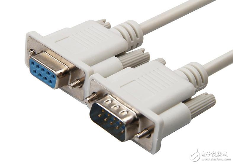
RS-232 is one of the most widely used serial communication interfaces, commonly found on personal computers. It is an asynchronous communication standard developed by the Electronic Industries Association (EIA). The RS-232 interface typically comes in two forms: a 9-pin (DB-9) or a 25-pin (DB-25) connector. Most PCs are equipped with two RS-232 ports, usually labeled as COM1 and COM2.
Despite its widespread use, the RS-232 interface has several limitations. First, it uses high signal voltage levels, which can easily damage sensitive circuitry. The logic levels are defined as -3V to -15V for a '1' and +3V to +15V for a '0'. This makes it incompatible with TTL logic levels, requiring level shifters when interfacing with microcontrollers or other digital systems.
Second, the transmission speed is relatively slow. In asynchronous mode, the maximum bit rate is around 20 kbps, which limits its use in high-speed applications. For example, on a 51 CPLD development board, the baud rate is often limited to 19200 bps.
Third, the interface uses a single-ended signaling method, where signals are transmitted over a common ground. This makes it vulnerable to common-mode interference, reducing noise immunity.
Lastly, the maximum transmission distance is only about 15 meters (50 feet), making it unsuitable for long-distance communication. For longer distances, alternatives like RS-422 or RS-485 are more appropriate.
Today, the most common RS-232 connectors are the 9-pin (DB9) and 25-pin (DB25) types. When the communication distance is short (up to 12 meters), a direct connection to the RS-232 port works well. However, for longer distances, a modem may be required. The simplest and most commonly used method is the three-wire system, which connects the transmit, receive, and ground lines.
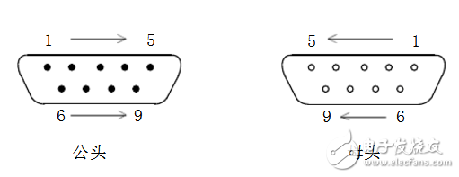
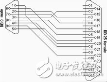
In a basic three-wire configuration, the receiving pin of one device is connected to the transmitting pin of another, and both share a common ground. For example, on a 9-pin serial port, pin 2 (receive) is connected to pin 3 (transmit). Similarly, on a 25-pin port, pin 3 (receive) is connected to pin 2 (transmit).
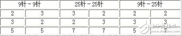
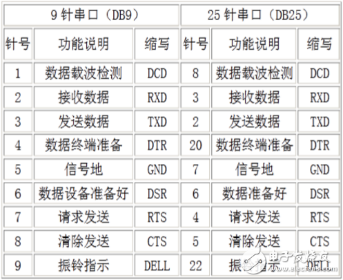
The table above shows the standard pinout for a PC's serial port. However, many non-standard devices, such as GPS modules or electronic compasses, may have different configurations. The key rule is to cross the receive and transmit pins and ensure that the signal grounds are properly connected. Understanding this principle helps in setting up reliable serial communication between various devices.