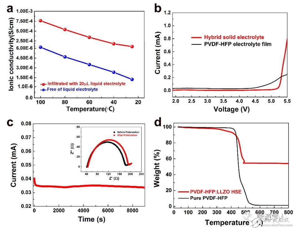
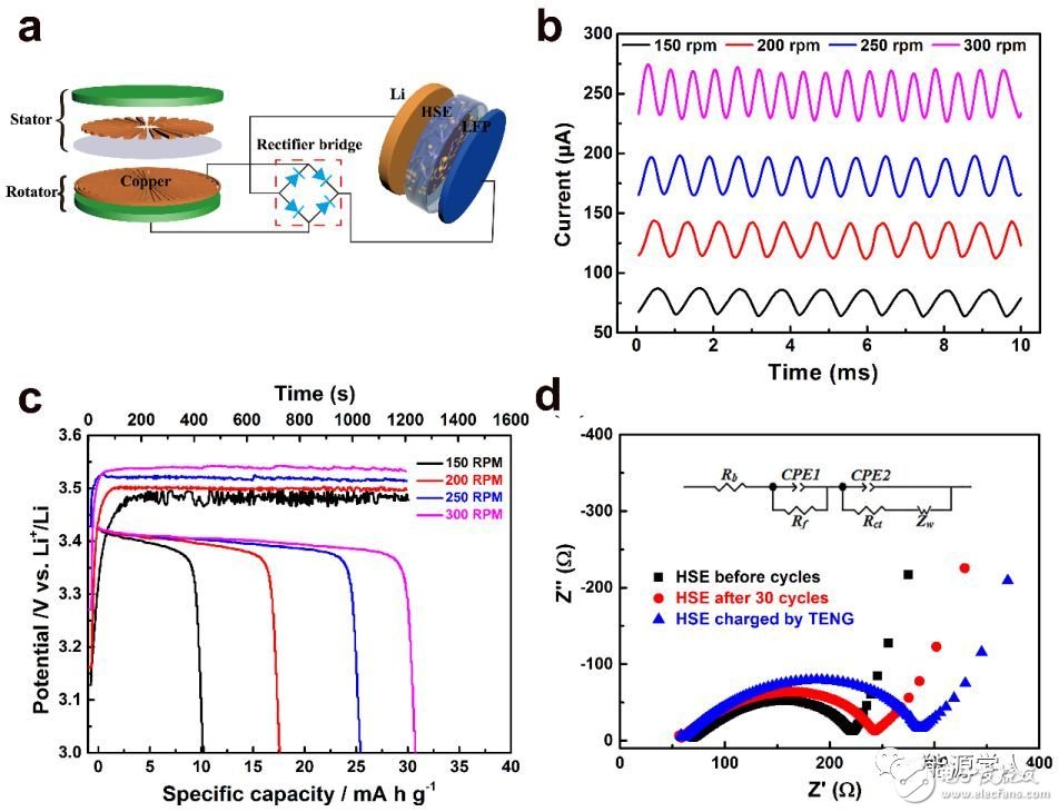
Lithium-ion batteries are widely used in mobile electronic devices, electric vehicles, and various energy storage devices due to their high energy density. However, the traditional lithium ion battery has a huge safety hazard due to the use of an organic liquid electrolyte. In recent years, solid electrolyte based solid electrolytes have attracted widespread attention due to their high energy density, longer cycle life, and better safety. Among many solid electrolytes, garnet-structured Li7La3Zr2O12 (LLZO) is a promising solid electrolyte due to its high room temperature ionic conductance, good thermal stability and good stability to metallic lithium anodes. . However, when it is used in a solid-state battery, there is a large interface resistance at the interface between the electrode and the electrolyte, and the machinability of the ceramic material is poor. Recently, Sun Chunwen, a researcher at the Beijing Institute of Nano Energy and Systems, Chinese Academy of Sciences, and Academician Wang Zhonglin (co-author) successfully prepared an organic/inorganic composite electrolyte membrane by casting. The composite electrolyte membrane has high ionic conductivity, good thermal stability, mechanical properties and flexibility. When it is used in a solid lithium battery electrolyte, LiFePO4 (LFP) is used as a positive electrode and lithium metal is used as a negative electrode. The prepared battery exhibited excellent cycle and rate performance. In addition, the coupling characteristics of the solid-state battery and the friction nano-generator are also studied. When the friction nano-generator with different frequency output charges the solid-state lithium battery, the higher the frequency is found, the charging platform of the battery becomes more stable. The article was published in the internationally renowned journal Nano Energy (Impact Factor: 12.343). Figure 1 is mainly a phase and morphology characterization of a composite solid electrolyte (HSE) film, wherein Figure 1a is an X-ray diffraction (XRD) pattern of the prepared LLZO powder. It can be seen that the prepared powder is a cubic phase of LLZO. Figure 1b is a scanning electron microscopy (SEM) photograph of the prepared LLZO powder. It can be seen that the particle size is about several micrometers. Figure 1c is an SEM photograph of the prepared HSE film. It can be seen that the LLZO particles are evenly distributed. In the PVDF-HFP polymer matrix. Figure 1d is a schematic diagram of ion transport of HSE. On the one hand, PVDF-HFP is a copolymer. In its amorphous region, F atoms are more electronegative and facilitate the transport of lithium ions in the amorphous region. On the other hand, LLZO The addition increases the number of ion transports of HSE. Figure 1. (a) XRD pattern of LLZO powder and composite electrolyte membrane prepared, (b) SEM photograph of LLZO powder, (c) SEM photograph of composite electrolyte membrane, (d) Lithium ion transport path in composite electrolyte membrane Schematic. Figure 2 a shows the conductivity of a 20 μL organic liquid electrolyte and a dry composite electrolyte membrane at different temperatures. It can be seen from the figure that the electrolyte membrane with 20 μL of organic liquid electrolyte has a room temperature ion conductance of 1.1 & TImes. 10−4 S/cm, up to 7.63 & TImes; 10−4 S/cm at 100 °C. The addition of LLZO powder not only provides a lithium ion transport path, but also reduces the crystallinity of the polymer matrix, thereby increasing the ionic conductivity of the composite film. Figure 2b compares the pure PVDF-HFP polymer film with the linear sweep voltammetry (LSV) curve of HSE. It can be seen that the pure polymer film decomposes at 4.5V (vs. Li+/Li), while HSE is added by LLZO powder. Its decomposition voltage can reach 5.3V. Fig. 2c is used to test the lithium ion migration number of the composite electrolyte membrane, and it is calculated that the ion mobility of the composite solid electrolyte membrane is as high as 0.61. Figure 2d shows the results of thermogravimetric analysis (TGA) of pure PVDF–HFP and composite electrolyte membranes. It can be seen that pure PVDF–HFP starts to decompose at 350 °C and completely decomposes at 500 °C. The composite electrolyte membrane with 50 wt% LLZO is added. The weight loss at 500 ° C is about 50 wt% and remains stable to 800 ° C. Figure 2. (a) Conductivity plot of 20 μL of organic liquid electrolyte and dry composite electrolyte membrane at different temperatures, (b) LSV comparison of pure PVDF-HFP polymer membrane and composite electrolyte membrane, (c) Li |HSE|Li symmetrical battery DC polarization test results for calculating lithium ion migration number, (d) TPV curve comparison of pure PVDF-HFP polymer film and composite electrolyte film. Figure 3a is a graph of charge and discharge curves of the prepared Li∣HSE∣LiFePO4 solid state battery at different rates. At 0.1 C, the battery discharge capacity can reach 140 mAh / g; when the current density increases to 0.5 C and 1.0 C, the battery discharge capacity is 113 mAh / g and 103 mAh / g, respectively. Figure 3b shows the rate performance of Li∣HSE∣LiFePO4 battery at room temperature. It can be seen that as the current density increases, the battery capacity decreases, which is mainly caused by the limited diffusion of lithium ions; but at a current density of 2 C The battery capacity can still reach 80mAh / g. Figure 3c shows the cycle performance of the battery at a current density of 0.5C (0.2 mA/cm2) at room temperature. It can be seen that the Coulomb efficiency is close to 100% after 180 cycles of the battery, and its capacity retention rate is as high as 92.5%. Figure 3. (a) The first charge and discharge curve of a solid lithium battery at different magnifications, (b) The specific discharge capacity of the battery at different rates with the number of cycles at 25 ° C, (c) 0.5 C rate , battery capacity and coulombic efficiency as a function of cycle times, (d) Li|HSE|Li symmetric battery voltage versus time at different current densities. Figure 4a is a schematic diagram of the charging of a solid-state lithium battery by a friction nano-generator (TENG). The effects of different frequency pulse output currents on the performance of a solid-state lithium battery are investigated. Figure 4b shows the output current curve of TENG at different speeds. Figure 4c shows the solid state lithium battery charged for 20 min at different speeds of TENG, and then the battery is discharged at a constant current of 40 μA. It can be seen that as the rotational speed increases, the charging current increases, and the battery charging capacity increases, especially at higher rotational speeds, the battery charging curve is more stable. Figure 4d shows the impedance spectrum of the battery after different rate cycling and the battery after charging with TENG. It can be seen that the charge transfer resistance (Rct) increases after charging with TENG, which may be due to the friction nanogenerator to the battery. When charging, the pulse current causes a change in the interface between the electrode and the electrolyte. The results show that the solid-state battery can stably store the pulse energy output from the friction nano-generator, especially the pulse energy at higher frequencies. Figure 4. (a) Schematic diagram of a triboelectric generator (TENG) charging a solid-state lithium battery, (b) TENG output current curve at different speeds, (c) TENG at different speeds to charge the solid-state battery for 20 min. The discharge curve of the battery with a current of 40μA, (d) the battery after cycling at different rates and the impedance spectrum of the battery after charging with TENG. Preparation of Li7La3Zr2O12(LLZO) powder by liquid phase method: 0.0248 mol citric acid (C6H8O7·H2O), 0.01224 mol ethylenediaminetetraacetic acid (C10H16N2O8), 0.007 mol lithium nitrate (LiNO3), 0.003 mol lanthanum nitrate (La(NO3) 3·6H2O), 0.00175 mol zirconium oxynitrate (ZrO (NO3)2·xH2O), 0.00024 mol aluminum nitrate (Al(NO3)3·9H2O) and 0.00025 mol bismuth oxalate (C2NbO4) dissolved in 40 ml of deionized water, magnetically stirred Dissolve, then add a certain amount of nitric acid, ammonia, and adjust the pH of the solution ≈8. After stirring at 80 ° C for 6 hours, the solvent was evaporated to obtain a sol, which was further dried in an oven to obtain a gel, which was then ground. Thereafter, the precursor was placed in a crucible, and calcined in a muffle furnace at 850 ° C for 2 h to obtain a cubic phase of LLZO powder. PVDF-HFP: Preparation of LLZO electrolyte membrane: Weigh 1.5g PVDF-HFP, add 9ml mixed solution of N,N-dimethylacetamide (DMAc) and acetone (volume ratio 1:2), stir and dissolve at normal temperature. Then, 1.5 g of LLZO powder was weighed and dispersed in the above suspension; the uniformly dispersed mixed slurry was scraped on a Teflon plate with a doctor blade, and the scraper blade gap was about 120 μm; after the room temperature solvent was naturally evaporated, The film was peeled off from the Teflon sheet, dried in an oven at 60 ° C for 12 h, and then placed in a vacuum oven at 60 ° C for 6 h; the obtained film was punched, and then pressed at a pressure of 6 MPa to prevent deformation of the electrolyte membrane. . Finally, the prepared electrolyte membrane was placed in an Ar gas filled glove box for use. Wenqiang Zhang, Jinhui Nie, Fan Li, Zhong Lin Wang, Chunwen Sun, A Durable and Safe Solid-State Lithium Battery with a Hybrid Electrolyte Membrane, Nano Energy, 45 (2018), DOI:10.1016/j.nanoen.2018.01.028 LED Lighting Zinc Alloy Die Casting Led Lighting Zinc Alloy Die Casting,Aluminum Alloys Die Casting,Aluminum Zinc Alloy Die Casting,Motor Housing Parts Casting Dongguan Metalwork Technology Co., LTD. , https://www.diecast-pro.com