5V Switching Wall Charger Power Adapter for Home Electronics
5v wall charger,5v 2a wall charger,5v 3a wall charger,5v power charger,switching 5v charger,5v 1a Wall Wart Transformer Charger,5v 2a Wall Wart Transformer Charger,5v 3a Wall Wart Transformer Charger,5V 2A/2000mah AC Power Adapter Adaptor Wall Charge Shenzhen Waweis Technology Co., Ltd. , https://www.waweis.com
Micro USB:
Original back-and-white display Kindle 1st Gen, Kindle Fire Kindle HD Fire HD 6 8 10 HDX 7 8.9 9.7, Samsung Galaxy S7/Edge, S6/Edge, S5, S4, S3, S2, Si9003, S5820, N7100, Note3, Note4
5.5mm x 2.1mm:
For Bluetooth speakers/ Electronic Toys/ Mini Fan/ Portable Air Conditioner/ LED Pixel Light/ Monitor/ Camera/ Webcam Router/ Cable Modem/ USB-HUB/ photo player/ SCM development/ access control attendance ect.
4.0mm x 1.7mm:
For mp3 mp4 speaker CCTV camera power supply connection/ digital picture frame/ shower Christmas lights/ Sabrent USB HUB/ digital recorder ect.
3.5mm x 1.35mm:
* For Facial Cleansing Brush: Foreo Luna 3/ Luna 3 Plus/ Luna/ Luna2/ Luna Mini/ Luna Mini 2/ Luna Go/ Luna Luxe, ISSA Series E-Toothbrush ISSA / ISSA Hybrid / ISSA mini / ISSA Mikro / ISSA play, ESPADA Acne Treatment Device, IRIS Eye Massager
* For Fairywill Sonic Electric Toothbrush FWP11 FW507 FWD1 FWD3 FWD8 FW917 FW2001 FWE11 FWE11 FW917 FWT9 ect.
* For LELO Ida, Lyla, Lyla 2, Oden, Oden 2, Ora, Ora 2, Tara, Alia, Isla, Soraya, Inez, Yva, Mia, Mia 2, Nea, Nea 2, Lily, Lily 2, Liv, Liv 2, Gigi, Gigi 2.
* For LELO Mona, Mona 2, Mona Wave, Ina, Ina 2, Ina Wave, Siri, Siri 2, Iris, Elise, Elise 2, Billy, Tor, Tor 2, Bo, Hugo, Bruno, Hula Beads, Loki, Loki Wave.
Designing a real-time analyzer for the ARINC659 bus based on FPGA
**Abstract**: As the complexity of aviation system integration continues to grow, effectively monitoring bus data behavior, performing real-time data analysis, and conducting fault diagnosis and localization have become critical challenges for avionics systems. This paper presents a design scheme for an ARINC659 bus analyzer based on FPGA technology. The system is capable of monitoring, sampling, storing, and performing fault injection tests on ARINC659 bus data. It enables real-time analysis of bus communication through its interface, providing a comprehensive and reliable testing solution for ARINC659 bus data.

**0. Preface**
The continuous development of avionics system integration has raised the demands for system security, fault tolerance, and real-time performance. The backplane bus plays a crucial role in data transfer between online replaceable modules (LRMs) in avionics systems. With the increasing complexity of aviation systems, it has become essential for avionics systems to monitor bus data behavior efficiently, analyze data in real time, and perform fault detection and localization. Implementing a system that can trigger transient monitoring to assess the communication status between LRMs can significantly improve maintenance efficiency and reduce the time required to resolve system faults, thereby enhancing equipment maintainability and availability [1].
This paper introduces a design for an ARINC659 bus analyzer system based on FPGA, which supports functions such as bus data monitoring, fault injection, and simulation testing.
**1. Program Design**
**1.1 Transmission Mechanism**
ARINC659 is a serial bus that uses four serial buses for half-duplex communication with cross-checking, reducing hardware complexity and improving reliability. It features a dual-bus configuration with two pairs of buses: A and B, each consisting of “x†and “y†channels. Each bus includes one clock line and two data lines, transmitting 2 data bits per channel. In total, the bus consists of 12 lines.
ARINC659 employs a dual-bus cross-detection fault-tolerant mechanism. Received data is first decoded, and then cross-correlated by comparing the validity of the received data with the four decoded bus data (AX=AY, BX=BY, AX=BY, AY=BX). The comparison results determine data validity using a call availability table or integrity table.
The command table is responsible for bus initialization, pre-decoding commands, and managing communication between nodes and task configurations within the system.
**1.2 Working Principle**
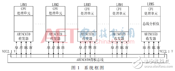
The bus analyzer is connected to the ARINC659 bus like other LRM modules. As shown in Figure 1, the bus analyzer shares the same command table as other LRMs. When set to analysis mode, it begins receiving all bus data once the system powers on and starts communication. It analyzes and processes both message and synchronization data, displaying real-time bus status via the host interface.
The bus analyzer only receives data and does not transmit or alter any data on the bus. According to ARINC659 specifications, only one transmitter can be active at a time, or a backup transmitter may send data. Multiple devices can receive data, and the bus analyzer is configured to operate in receive-only mode. It receives data through the bus transceiver and samples it at a frequency of 240 MHz. The acquisition module performs front-end processing, sends the data to the processor for protocol and data analysis, and transmits the bus state over Ethernet to the application layer software. The GUI interface then displays real-time bus status after processing.
In fault injection mode, the bus analyzer acts as an input device, simulating open-circuit or low-level faults, which can induce bus errors [2].
After power-on initialization, the bus analyzer follows the ARINC659 specification and enters a monitoring state, transmitting real-time bus data to the host for analysis and display.
**1.3 Hardware Design**
The ARINC659 bus analyzer consists of a power supply circuit, reset circuit, bus transceiver circuit, bus relay circuit, data acquisition unit (FPGA and configuration circuit), and a CPU data processing unit. As shown in Figure 2, the data acquisition unit handles high-frequency sampling of bus data, while the CPU data processing unit processes the data and sends the bus status to the host in real time. The CPU requires a memory-equipped module with PCI and Ethernet interfaces.
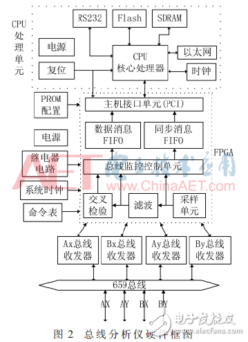
The power circuit supplies the necessary voltage for all components of the system. The reset circuit supports three modes: manual, power-on, and soft reset, ensuring system stability and reliability.