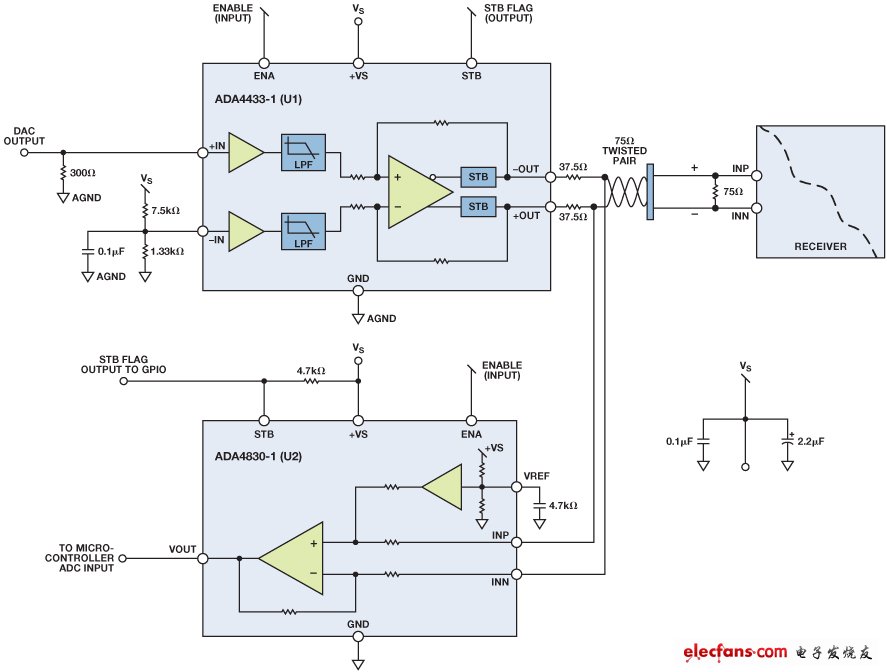
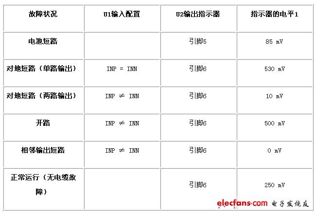
As a key component of modern cars, wire harnesses include thousands of mounting components that connect individual electronic systems together so they can work together. A minor fault in any harness can have an effect on the overall system. However, in order to cope with the increasing demand for internal electronic systems of vehicles, the complexity of automotive wiring harnesses is also increasing, and we are more urgently required to quickly and easily detect open and short circuits. Line diagnostics are very important throughout the life of the vehicle. From the installation phase, diagnosing and repairing line faults can result in severe manufacturing delays. In the operational phase, diagnostic and repair line failures can result in an increase in the number of vehicle repairs, which can significantly increase the manufacturer's warranty costs. Active safety systems, including lane detection and parking assistance systems (front and rearview cameras), and infotainment systems (including navigation and rear seat entertainment) are automotive electronics systems that are of greater concern. For these systems to operate efficiently, video data transmitted over the cable from any corner of the car must be reliably transmitted to the driver and passengers. Cable health is critical to maintaining the proper functioning of these systems. This paper presents a circuit concept that provides reliable, cost-effective technology for implementing diagnostics on video and audio transmission lines for automotive applications. The circuit shown in Figure 1 can effectively detect battery short (STB), short to ground (STG), open and short circuit faults. The circuit uses the ADA4433-1 (U1) fully integrated video reconstruction filter as part of the video transmission signal chain and also uses the ADA4830-1 (U2) high speed differential amplifier as the detection circuit. The ADA4433-1 incorporates a high-order filter with a -3 dB cutoff frequency of 10 MHz, 45-dB rejection at 27 MHz, and an internal fixed gain of 2 V/V. It features excellent video features, overvoltage protection (OVP) and overcurrent protection (STG) on the output, and low power consumption. The ADA4830-1 provides an attenuation gain of 0.50 V/V and a fault detection output flag indicating the presence of an overvoltage condition on its input. It offers input overvoltage protection up to 18 V, a wide input common-mode voltage range and excellent ESD stability. In the example circuit shown in Figure 1, U1 represents a differential output buffer that transmits video signals from a rear view camera or engine control unit (ECU) to the receiver. The input is typically driven by a CMOS imaging element or video encoder. The main function of U1 is to provide active filtering (reconstruction) and drive the transmission of video signals through the cable to the display. The input of U2 is connected to the output of U1 to provide the fault detection functions listed in Table 1, which will be explained in the following paragraphs. Figure 1. Line diagnostic circuitry using the ADA4433-1 (U1) and ADA4830-1 (U2). Battery short circuit fault detection Both U1 and U2 have integrated battery short detection and STB output flags. In a battery short event, U2's output flag will signal a logic low state, which can be easily read by the microcontroller's general purpose input/output (GPIO) port. Ground short circuit fault detection (single output) Connect the positive input (INP) of U1 to the negative input (INN). +OUT and? The differential output between OUT should be 0 V. If either output is shorted to ground, the differential voltage at the U2 output should be greater than 500 mV. Ground short circuit fault detection (two outputs) Set the positive input (INP) of U1 to 0 V.+OUT and ? The differential output between OUT should be approximately 1 V. If both outputs are shorted to ground, the differential voltage at the U2 output is approximately 0 V. open circuit Set the positive input (INP) of U1 to 0 V.+OUT and ? The differential output between OUT should be approximately 1 V. If there is a short open connection, the differential voltage developed at the output of U2 is approximately 500 mV. Adjacent output short circuit Set the positive input (INP) of U1 to 0 V.+OUT and ? The differential output between OUT should be approximately 1 V. If the two outputs are shorted together, the differential voltage developed at the output of U2 is approximately 0 V. Normal operation (no cable failure) Set the positive input (INP) of U1 to 0 V.+OUT and ? The differential output between OUT should be approximately 1 V. The differential voltage developed at the output of U2 is approximately 250 mV. Table 1. Summary of diagnostic output indicators
App Control Window Cleaning Robot
China Window Washing Robot , Glass Cleaning Robot ,Automatic Window Cleaner Robot,App Control Window Cleaning Robot, we offered that you can trust. Welcome to do business with us.China window clean robot manufacture and big supplier, best quality and good price.
2019 APP Window Clean Robot ,smart clean robot. Window Cleaning Robot Video welcome to see our youtube.
if you have any require window cleaning robot wireless,please let me know,thanks
App Control Window Cleaning Robot Window Washing Robot,Glass Cleaning Robot,Automatic Window Cleaner Robot,App Control Window Cleaning Robot,Window Cleaning Robot Video Zhengzhou Bangmi Smart Technology Co., Ltd. , https://www.globalcleanrobot.com