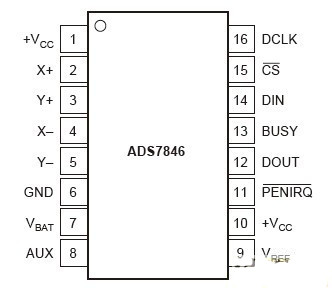
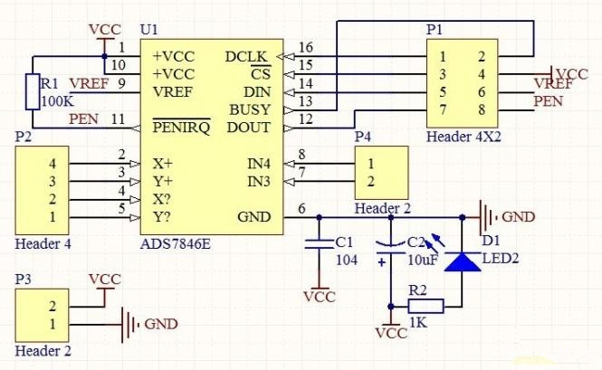
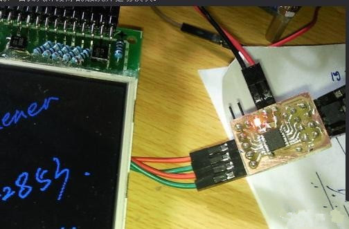
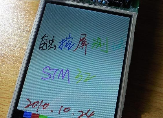
Touch screens are nothing new. Today's electronic products basically come with a large color LCD, plus a touch-sensitive touch screen. It is very convenient to use and can completely replace the fixed buttons of the past. This article refers to the address: http:// The following is a description of the driving circuit of a touch screen. I also made this small board an hour ago. After the test is successful, I will publish this log immediately. It is hot and hot! First, the following structure of the touch screen is introduced, which is bonded by a touch screen and a liquid crystal display screen. The liquid crystal display screen is classified according to various methods such as color, material, imaging principle, etc. There is a wide variety of LCD screens. The 16Bit translucent reflective TFT LCD dot matrix display is used in this picture. The touch screen is mainly divided into two categories, namely capacitive and resistive. The capacitive touch screen utilizes the current sensing of the human body to work. The advantage is that the service life is long, the force is not required when the touch is made, and the panel is hard and wear-resistant; the disadvantage is that the touch precision is low, and a specific medium touch (such as human skin) must be used. Temperature and humidity have a great influence. When there is a strong magnetic field in the outside world, the touch screen will malfunction. In short, the anti-interference is poor. The resistive touch screen is positioned by the resistance values ​​of the vertical axis and the horizontal axis when pressed. The advantage is that the anti-interference is good, the touch precision is high, and the object can be touched by any object. The disadvantage is that the surface is a plastic film, which is easy to wear and touch. It is necessary to press a little bit. The resistive touch screen used in this article. Next, I will introduce some touch screen control ICs: ADS7846, ADS7843 and TSC2046, which are the most common four-wire touch screen control chips, all of which are BURR-BROWN (already acquired by TI, when looking for a package library, go to TI) The company's products, the three pins are compatible with each other, but the on-chip functions are different, such as integrated temperature sensing in the 7846, detectable touch pressure and other functions, please refer to DataSheet. TSC2046 is a new control chip. Because its domestic film is cheap (retail is about 1 yuan/piece), it is widely used in domestic electronic products such as MP3 and mobile phones with touch screen. I used the ADS7846 this time. ADS7846 pin diagram: Pin function introduction: DCLK: clock input port CS: Chip select signal DIN: serial data input, when CS is low, data is latched on the rising edge of DCLK BUSY: Busy signal output, when CS is high, it is high impedance DOUT: serial data output, high impedance when CS is high PENIRQ: Pen interrupt (interrupt signal is generated when the screen is touched) Vref: reference voltage (usually connected directly to VCC) Vbat: power detection input (generally not used) AUX: Alternative input (usually not used) X+, Y+, X-, Y-: four-wire touch screen position input The idea of ​​the program is to refer to a netizen, I transplanted it. Working principle: Each time the touch screen is pressed, the PEN pin of the ADS7846 will be pulled low, triggering the STM32 interrupt, and then processing the function to be executed in the interrupt service routine. The principle of drawing is to continuously sample the X and Y coordinates ten times in the interrupt. If it is not enough for ten times, do nothing. After getting ten times of data, sorting is performed, and the data of the middle three times is used to calculate the mean value, and the required X and Y coordinates are obtained. After getting the touch screen point, then draw a point on the corresponding point on the screen. The following is a schematic of the circuit: Plate made by sensitization (uncut): After cutting out the middle part, it is smaller with a dollar coin, and the right side is a negative film printed on sulfuric acid paper. I wrote an artboard with an optional brush and background color: Finally, the STM32 touch screen driver (added artboard function) is written in C language, which is easy to transplant. Interested students can move it to 51 or other MCUs to run. The complete code is downloaded from here http://dl.21ic.com/download/chumo1-rar-ic-106798.html #include"hx8347.h" //I created the LCD screen file, this header file only defines some basic variables. Does not involve driver related functions / / Define the pin high and low #define ADS_DCLK_H() GPIO_SetBits(GPIOB, GPIO_Pin_6) // ADS7846 clock signal #define ADS_DCLK_L() GPIO_ResetBits(GPIOB, GPIO_Pin_6) #define ADS_CS_H() GPIO_SetBits(GPIOB, GPIO_Pin_7)//ADS7846 Chip Select Signal #define ADS_CS_L() GPIO_ResetBits(GPIOB, GPIO_Pin_7) #define ADS_DIN_H() GPIO_SetBits(GPIOB, GPIO_Pin_8) #define ADS_DIN_L() GPIO_ResetBits(GPIOB, GPIO_Pin_8) #define ADS_DOUT GPIO_ReadInputDataBit(GPIOB, GPIO_Pin_9) #define ADS_PEN GPIO_ReadInputDataBit(GPIOB, GPIO_Pin_10)////ADS7846 response signal / / Initialize the I / O port Void ADS_GPIO_Config() { GPIO_InitTypeDef GPIO_InitStructure; RCC_APB2PeriphClockCmd(RCC_APB2Periph_GPIOB, ENABLE); GPIO_InitStructure.GPIO_Pin = GPIO_Pin_6|GPIO_Pin_7|GPIO_Pin_8; GPIO_InitStructure.GPIO_Mode = GPIO_Mode_Out_PP; GPIO_InitStructure.GPIO_Speed ​​= GPIO_Speed_50MHz; GPIO_Init(GPIOB, &GPIO_InitStructure); RCC_APB2PeriphClockCmd(RCC_APB2Periph_GPIOB, ENABLE); GPIO_InitStructure.GPIO_Pin = GPIO_Pin_9|GPIO_Pin_10; GPIO_InitStructure.GPIO_Mode = GPIO_Mode_IN_FLOATING; GPIO_Init(GPIOB, &GPIO_InitStructure); } Void ADS_Spi_Start()//Initial signal { ADS_CS_H(); ADS_DCLK_H(); ADS_DIN_H(); } Void ADS_Write_Byte(u8 num) { U8 count=0; ADS_DCLK_L(); For(count=0;count<8;count++) { If(num&0x80) ADS_DIN_H(); Else ADS_DIN_L(); Num<<=1; ADS_DCLK_L(); ADS_DCLK_H(); // rising edge is valid } } U16 ADS_Readdata() { U16 num; U8 count; For(count=0;count<12;count++) { Num<<=1; ADS_DCLK_H(); ADS_DCLK_L(); If(ADS_DOUT) Num++; } Return num; } #define CMD_RDX 0X90 //0B10010000 Read the X coordinate in differential mode #define CMD_RDY 0XD0 //0B11010000 Read the Y coordinate in differential mode U16 X=0, Y=0;//current touch coordinates U8 Readonce() { ADS_Spi_Start(); ADS_CS_L(); ADS_Write_Byte(CMD_RDX); ADS_DCLK_H(); Delay_us(3); ADS_DCLK_L(); Delay_us(3); Y=ADS_Readdata(); ADS_Write_Byte(CMD_RDY); ADS_DCLK_H(); Delay_us(1); ADS_DCLK_L(); Delay_us(1); X=ADS_Readdata(); ADS_CS_H(); If(X>100&&Y>100&&X<3800&&Y<3800)return 1;//Read successful (range limit) Else return 0; / / read failed } Void drawbigpoint(u8 x,u16 y,u16 col) { If(x>220&&y<9) { LCD_DrawBlock (0,0,239,319,0x0000);//clear screen LCD_write_english_string(210,0,"CLR",0xFFE0,0x001F);//clear screen area } Else { LCD_Set_Point(x,y,col);//center point LCD_Set_Point((x+1), y, col); LCD_Set_Point(x,(y+1),col); LCD_Set_Point((x+1), (y+1), col); } } / / Read ADS7846 (line drawing) Void Read_Ads7846(void) { U8 t, t1, count=0; U16 databuffer[2][10]={{5,7,9,3,2,6,4,0,3,1},{5,7,9,3,2,6,4,0,3 ,1}}; / / Data group U16 temp=0; / / Cycle reading 10 times Do { t=ADS_PEN; //Touch screen is pressed, PEN is L If(Readonce()) //The reading is successful { Databuffer[0][count]=X; Databuffer[1][count]=Y; Count++; } } While(!t&&count<10); If(count==10)//Read 10 times valid { //X ascending order Do { T1=0; For(t=0;t { If(databuffer[0][t]>databuffer[0][t+1])//ascending order { Temp=databuffer[0][t+1]; Databuffer[0][t+1]=databuffer[0][t]; Databuffer[0][t]=temp; T1=1; } } } While(t1); Do//Y ascending order { T1=0; For(t=0;t { If(databuffer[1][t]>databuffer[1][t+1])//ascending order { Temp=databuffer[1][t+1]; Databuffer[1][t+1]=databuffer[1][t]; Databuffer[1][t]=temp; T1=1; } } } While(t1); X=(databuffer[0][3]+databuffer[0][4]+databuffer[0][5])/3; Y=(databuffer[1][3]+databuffer[1][4]+databuffer[1][5])/3; / / According to the specific parameters of the touch screen If(X<=4000&&Y<=4000) { If(X>=240) X-=240; Else X=0; If(Y>=320) Y-=320; Else Y=0; Drawbigpoint (X/15, Y/11+10, BLUE); } } } Void EXTI1_IRQHandler(void) { U8 t=0; / / Eliminate jitter Do { Delay_us(10); t=ADS_PEN; Read_Ads7846(); } While(t==0); EXTI_ClearITPendingBit(EXTI_Line1); } / / interrupt priority management / open Void NVIC_Configuration(void) { NVIC_InitTypeDef NVIC_InitStructure; //Memory map #ifdef VECT_TAB_RAM NVIC_SetVectorTable(NVIC_VectTab_RAM, 0x0); #else NVIC_SetVectorTable(NVIC_VectTab_FLASH, 0x0); #endif NVIC_PriorityGroupConfig(NVIC_PriorityGroup_0);//Priority is divided into Group 0 for a total of 5 groups NVIC_InitStructure.NVIC_IRQChannel = EXTI1_IRQChannel; //Use external interrupt 1 NVIC_InitStructure.NVIC_IRQChannelPreemptionPriority = 1;//Class 1 NVIC_InitStructure.NVIC_IRQChannelSubPriority = 0; NVIC_InitStructure.NVIC_IRQChannelCmd = ENABLE; NVIC_Init(&NVIC_InitStructure); } / / External interrupt initialization Void EXTI_Configuration(void)//Configure external interrupt { EXTI_InitTypeDef EXTI_InitStructure; / / declare the interrupt library function structure EXTI_InitStructure.EXTI_Line = EXTI_Line1; //External Interrupt Channel 1 EXTI_InitStructure.EXTI_Mode = EXTI_Mode_Interrupt; //Interrupt mode EXTI_InitStructure.EXTI_Trigger = EXTI_Trigger_Falling; // Falling edge trigger EXTI_InitStructure.EXTI_LineCmd = ENABLE; //Enable EXTI_Init(&EXTI_InitStructure); GPIO_EXTILineConfig(GPIO_PortSourceGPIOB, GPIO_PinSource10); / / Set external interrupt channel 1 to PB10 } //END
All auto filters are designed to prevent harmful debris from
entering any parts where air and fluid flows, including your engine, radiator,
fuel lines and more. Once a filter is no longer performing its intended
function, decreased performance-even engine damage-can result.
When your air
filter is dirty, your engine is forced to work harder, resulting in poor fuel
economy, higher emissions and, possibly, a loss of engine power. In turn, as a
worst-case scenario, a clogged Cabin Air Filter can lead to under-performance
of the A/C system, causing weak air flow from the cabin vents. It can also lead
to unwanted, unfiltered air in the cabin. As for a mucked-up fuel filter,
that`ll land you with a weakened fuel supply to injectors, a reduction in
engine power, poor acceleration and lousy fuel economy-not to mention a
potential breakdown.
They protect vital
car parts by keeping harmful debris at bay so your car runs right. Filters also
ensure your car runs more efficiently. The cleaner your filter, the more it
allows for the maximum flow of air or fluid through the system. Like a clogged
drain, a dirty filter starves the system of the vital air or fluid and makes
each system it protects work harder to do its job. Once filters are dirtied,
they should be replaced.
it`s recommended
that you get your filters replaced every 12 months or 12,000 miles, but check
your owner`s manual for specifics about your vehicle`s filter replacement
schedules.
Automotive Filter,Car Air Filter,Car Cabin Air Filter, Car Oil Filter Donguan Bronco Filter Co., Ltd , https://www.broncofilter-cn.com