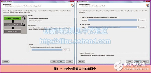
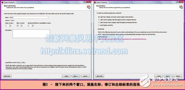
One of the key benefits of the Zynq SoC architecture is its ability to enhance processing performance by implementing custom peripherals within the programmable logic section. This integration allows for greater flexibility and efficiency in system design, especially when working with Xilinx's Zynq-7000 All Programmable SoC. While it may initially seem complex, designing your own peripherals on the programmable logic (PL) side can actually be quite straightforward. By leveraging the PL to handle specific tasks, you can significantly improve the performance of the processing system (PS) or even control the behavior of the PL from the PS side. For instance, the PS can interact with memory-mapped registers on the PL to manage various functions, such as controlling LED patterns or sensor inputs. To demonstrate this process, we will create a simple module that controls the memory-mapped LEDs on the ZedBoard. Using Xilinx PlanAhead, XPS, and the Software Development Kit (SDK), we will go through three main steps: creating the peripheral in an EDK environment, writing the VHDL code, and developing the software application that interacts with the custom module. Step 1: Create a Module in the EDK The first step involves opening Xilinx Platform Studio (XPS) from the PlanAhead project that includes the Zynq SoC design. From the menu, select "Hardware > Create or Import Peripheral" to begin the process. For our example, we will design a module that controls a walking LED display on the ZedBoard, where one LED is controlled by software while the others follow a sequential pattern. Although not the most advanced use case, this example provides a clear and practical demonstration of how to build custom peripherals. During the creation process, you'll be guided through a series of wizard windows. The first few screens ask whether you want to create a new peripheral or import an existing one, and which project to associate it with. You’ll then name the module, set the version, and define the revision. Note that you can later re-customize the module using the *.cip file via the options at the bottom of the peripheral flow. Next, you’ll choose the AXI bus type. In our case, we selected the AXI4-Lite interface, which is ideal for simple memory-mapped control registers. This allows the PS to read and write to the registers via the AXI bus. A few basic registers are created automatically, and they reside in the programmable logic section of the Zynq SoC. These registers can be accessed through user logic applications that implement the peripheral functionality. The next six steps allow you to configure the AXI master or slave settings, define the number of registers, and customize support files. For our example, we used a single register in slave mode. One of the most useful features is the option to generate template driver files, which simplifies communication between the PS and the peripheral. In the final step, XPS generates several files essential for creating and using the new peripheral, including top-level VHDL files, user logic files, peripheral description files, CIP files for re-customization, SDK driver files, and more. These files are stored in the PlanAhead source directory, typically under zed_blog.srcs/sources_1/edk/proc_subsystem. Step 2: Create RTL Logic Within the Pcores directory, you’ll find two key files: one named after your component (e.g., led_if.vhd) and another called user_logic.vhd. You can implement your design in the user_logic.vhd file. The wizard has already generated the necessary registers and interfaces for communication over the AXI bus. You can also instantiate additional modules in the led_if.vhd file, ensuring any changes to the entity are reflected in the port map. If external ports are required, such as for controlling LEDs, those must also be included in the port map. After completing the logic design, it’s a good idea to simulate it to verify that it works as expected. The bus function model is available in the Pcores/devl/bfmsim directory, making it easy to test the peripheral before integrating it into the full system. Nomex Self Closing Sleeve,Nomex Split Braided Sleeve ,Nomex Self Closing Wrap,Nomex Cable Protection Sleeve,Nomex Split Cable Sleeve Dongguan Liansi Electronics Co.,Ltd , https://www.liansisleeve.com