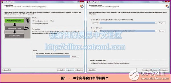
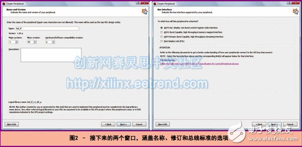
One of the key benefits of the Zynq SoC architecture is its ability to enhance processing performance by integrating custom peripherals into the programmable logic (PL) section of the device. This allows for a more efficient and flexible system design, where complex operations can be offloaded from the processing system (PS) to the PL. The Xilinx Zynq-7000 All Programmable SoC offers a powerful platform that combines a dual-core ARM Cortex-A9 processor with FPGA fabric. By leveraging the PL to implement custom peripherals, developers can significantly boost the performance of their applications. At first glance, this might seem like an added complexity, but in reality, it's a straightforward process once you understand the tools and workflow. Integrating peripherals into the PL can be especially beneficial when optimizing the PS or controlling behavior on the PL side. For example, the PS can use memory-mapped registers to manage the operation of the PL, enabling dynamic control over hardware functions. This makes the system more adaptable and responsive to changing requirements. To demonstrate this process, we've selected a simple example: controlling the LEDs on a ZedBoard using a custom peripheral. We'll walk through the steps of creating the module using Xilinx PlanAhead, XPS, and SDK. This example will help illustrate how to build and integrate custom peripherals into the Zynq architecture. The process involves three main steps: first, creating the peripheral in the Embedded Development Kit (EDK) environment; second, writing the VHDL code for the module and building the system; and third, developing software that interacts with the custom module. Creating a Peripheral in the EDK To begin, open Xilinx Platform Studio (XPS) from your PlanAhead project that includes the Zynq SoC design. Then, navigate to the menu option "Hardware > Create or Import Peripheral." This starts the wizard that guides you through the creation of a new peripheral. Our example involves a module that controls the walking LED display on the ZedBoard. While not the most advanced application, it serves as a great learning tool. It demonstrates how to create a custom peripheral that can be controlled via software, offering a clear understanding of the integration process. During the setup, you’ll go through several wizard screens. The first two ask whether you want to create a new peripheral or import an existing one and which project to associate it with. Next, you’ll name the module and define its version and revision. You can also re-customize the module later by reading back the *.cip file. After naming the module, you’ll select the AXI bus type. In our case, we chose AXI4-Lite for a simple memory-mapped control interface. This allows the PS to read and write to registers on the PL side. These registers are part of the PL and can be accessed through user logic applications. They serve as a bridge between the PS and the custom hardware. The next set of wizard pages lets you configure the AXI master or slave settings and define the number of registers needed. In our example, we used one register in slave mode. Enabling the "Generate Template Driver Files" option is highly recommended, as it provides source and header files that simplify communication between the PS and the peripheral. Finally, XPS generates several files that facilitate the creation and use of the new peripheral. These include top-level VHDL files, user logic files, peripheral description files, CIP files, and driver files for the SDK. All these files are stored in the PlanAhead source directory. The Pcores folder contains the files required by XPS and PlanAhead, while the driver folder holds the SDK-related files. This separation ensures a clean and organized development workflow. Creating RTL Code Inside the Pcores directory, you'll find two main files: one named after your peripheral (e.g., led_if.vhd) and another called user_logic.vhd. You can implement your design in the user_logic.vhd file. The wizard has already generated the necessary AXI interfaces and registers for communication. If your design requires external ports—such as controlling LEDs—you must update the port map accordingly. Any changes made to the user_logic.vhd entity should be reflected in the port mapping to ensure proper functionality. Once the logic is implemented, you can simulate it to verify its correctness. The bus function model is available in the Pcores/devl/bfmsim directory, making it easy to test your design before deployment. An electromagnetic interference shield sleeve is a protective layer used to shield electronic components from electromagnetic interference (EMI). Mainly tinned copper, copper core and other materials can be selected, widely used in electronics, aircraft, ships, industry and fuel vehicles and new energy vehicles wiring harness system shielding and safety protection. Compared with tinned copper, copper core material also has the function of electromagnetic signal shielding, and is more lightweight, better softness, customers can choose different materials according to their own needs. If it is applied to the automobile, the soft connection tinned copper strip is also a suitable choice. The soft connection tinned copper strip is made of polyester composite wire and polyester monofilm, which is spun by the weft and yarn spinning machine. It meets the environmental protection certification such as RoHS, REACH, halogen free, etc. It is soft, lightweight, and has the function of excellent wear resistance, noise reduction and finishing. EMI Sheilding Sleeving,Crochet Copper Mesh Braided Sleeve,Tinned Copper Braided,Tinned Copper Sleeve Dongguan Liansi Electronics Co.,Ltd , https://www.liansisleeve.com