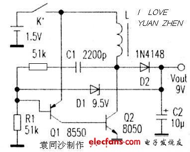
The 1.5V to 9V power supply circuit is illustrated in the diagram. This circuit is a basic oscillation-based boost design. BG1, along with L1, L2, and C1, forms an oscillator. BG1 acts as the switching transistor, operating in a high-frequency oscillation mode. L1 and C1 are feedback components that help sustain the oscillation, while L2 serves as the energy storage winding. To enhance convenience, the circuit also includes an automatic electronic switch made from BG3. When there's no load connected, BG3 remains off, which in turn keeps BG2 and BG1 in the cut-off state, stopping the entire circuit from consuming power. As a result, this design doesn't require a separate power switch. When points A and B are connected to a load, BG3 turns on, activating BG2. The load provides base current to BG1, turning it on. Energy flows into L2, where it is stored. At this point, BG1’s collector voltage drops significantly, causing D1 to be reverse-biased, and the load is powered by the residual voltage of C2. When BG1 turns off, the current through L2 cannot change abruptly, generating a higher back-EMF. This is rectified by D1 and output. Once the output voltage exceeds the regulation value of D2, the base-emitter junction of BG2 becomes reverse-biased, reducing BG1’s base current. This weakens the oscillation, lowering the output voltage until it stabilizes near D2’s regulation value. For BG1, choose an NPN silicon transistor with low saturation voltage, such as 9013 or 8050, requiring ICM ≥ 300mA and β ≥ 200. BG2 can be a PNP transistor like 9012 or 9015, while BG3 should be an NPN type like 9014. The smaller the leakage current, the better. L1 and L2 should be wound on a high-frequency 8mm magnetic ring (taken from an old electronic ballast or energy-saving lamp), using 0.1mm enameled wire. L1 has 6 turns, and L2 has 36 turns. I used this circuit to power a DT890A digital multimeter. The measured working current was below 45mA for the buzzer and 20uF/2uF capacitor blocks, and under 25mA for other ranges. When the battery voltage dropped to 0.9V, only the buzzer block showed high current consumption, while the 20uF and 2uF blocks displayed low voltage. The rest of the ranges worked fine. This circuit is simple to build, stable, cost-effective, and requires no tuning—just correct wiring ensures it works properly. Digital multimeters often need a separate power switch when using a 1.5V battery to generate 9V via a boost circuit. This can be inconvenient. However, the circuit described here automatically starts or stops based on the presence of the multimeter’s operating current. Thus, once connected to the booster’s output, the multimeter’s own power switch can be used without additional controls. C1 plays a role in positive feedback. When Q2 turns on, the positive feedback from C1 causes Q2 to quickly enter the saturation region. Then, C1 discharges and begins to charge in the opposite direction. As the base potential of Q1 increases, the base current of Q2 decreases, allowing the current through L1 to rise continuously. When this current becomes large enough to push Q2 out of saturation, the collector potential of Q2 rises, triggering the positive feedback from C1 to increase the base potential of Q1. This causes both Q1 and Q2 to immediately return to the cut-off state. Q1 then turns on again, and R1 and C1 recharge to lower the base potential of Q1. This process takes longer than the discharge phase, so the charging time of L1 is typically much longer than the discharge time. When D1 is connected, if the output voltage becomes too high, it can affect the charging and discharging of C1, resulting in shorter on-time for Q1 and Q2 and longer waiting periods after each discharge. As seen from the analysis, the operating frequency of this circuit depends mainly on R1 and C1, though L1 also has some influence, albeit minor. The driving capability of the circuit is determined by R1, L1, and the gain of Q1 and Q2. This circuit is easy to start, and the conditions for no oscillation are: R1 is relatively small. After Q1 and Q2 are turned on, C1 completes its reverse charging, and the current through Q1 reaches a minimum. If Q2 is still in the saturation region (due to L1’s internal resistance limiting further increase in collector current), it consumes a lot of power, causing the circuit to stop operating.
Power Meter is a monitoring and testing
instrument which determines the power consumption of a connected
appliance and the cost of the electricity consumed.
Installing the batteries
Install 3.6V rechargeable Battcrics(NI-MH) . The purpose of the batteries is to store the total electricity and mcinory setting.
Resetting
If an abnormal display appears or the
buttons produce no response, the instrument must be reset. To do
this,press the RESET button.
Display Mode
Entire LCD can be displayed for about 1
minute and then it automatically gets into Model. To transfer from one
mode to the other, press the FUNCTION button.
Mode 1: Time/Watt/Cost Display Display
duration(how long) this device connect to power source.LCD on first
line shows 0:00 with first two figures mean minutcs (2 figures will
occur while occur at 10 min) and the rest shows seconds. After 60mins,
it displays 0:00 again with first two numbers meas hour(2 figures will
occur at 10hours) and the rest shows minutes. The rest can be done in
the same manner which means after 24 hours, it will rc-caculatc. LCD on
second line displays current power which ranges in 0.0W~9999W. LCD on
third line displays the current electricity costs which ranges in
0.0cost~9999cost. It will keep on O.OOcost before setting rate without
other figures.
Mode 2: l ime/Cumulative electrical quantity Display Display duration(how long) this device connect to power source.
LCD on first line shows 0:00 with first
two figures mean minutes(2 figures will occur while occur at 10 min) and
the rest shows seconds. After 60mins, it displays 0:0() again with
first two numbers meas hour(2 figures will occur at 10hours)and the rest
shows minutes. The rest can be done in the same manner which means
after 24 hours, it will re-caculate. LCD on second line displays current
cumulative electrical quantity which ranges in 0.000K WH 〜 9999KWII
without other figures. LCD on third line displays''DAY''- "1 "will be
showed on numerical part(thc other three
figures will be showed at carry) which means it has cumulated
electrical quantity for 24hours(one day). The rest can be done in the
same manner untial the maximal cumulative time of 9999 days.
Mode 3: Time/Voltage/Frequency Display
LCD on first line displays the same as Mode 1 dones. LCD on second line
displays current voltage supply (v) which ranges in 0.0V~9999V .LCD on
third line displays current frequency (HZ) which ranges in 0.0HZ~9999HZ
without other figures.
Mode 4: Time/Current/Power Factor Display LCD on first line displays the same as Mode 1 dones.
LCD on second line displays load current
which ranges in 0.0000A~9999A. LCD on third line displays current power
factor which ranges in 0.00PF 〜 1 .OOPF without other figures.
Mode 5:Time/Minimum Power Display LCD on first line displays the same as Mode 1 clones. LCD on second
line displays the miniinum power which ranges in 0.0W~9999W. LCD on
third line displays character of "Lo" without other figures.
Mode 6: I,ime/Maximal Power Display LCD on first line displays the same as Mode 1 dones. LCD on second line
displays the maximal power which ranges in 0.0W~9999W. LCD on third
line displays character of "Hi" without other figures.
Mode 7: Time/Price Display LCD on first line displays the same as Mode 1 dones. LCD on third line
displays the cost which ranges in O.OOCOST/KWH 〜 99.99COST/KWH without
other figures. Power Meter Double Rates, Power Meter Two Rates, Cost Rate Socket, Power Meter Cost Rate, Energy Meter Cost Rate, Cost Socket, Cost Plug NINGBO COWELL ELECTRONICS & TECHNOLOGY CO., LTD , https://www.cowellsockets.com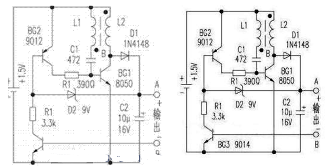
Overload Display: When the power socket connects the load over 3680W, LCD on second line
displays the"O VER LOAD" with booming noise to warn the users,( 1918935, 60470643,
60469303,selectable choice)
Supplemental informations:
1: Except tt OVERLOAD , ' interface, LCD on first line display time in repitition within 24hours.
2: LCD on first line, second line or third
line described in this intruction take section according to two black
lines on LCD screen. Here it added fbr clarified purpose.
3. Mode 7 will directly occur while press down button "cost".
4. [UP"&''Down" are in no function under un-setting mode.
Backlight Mode:
Connect to AC power,backlight im mediately light,if not press any button,backlight will went off in 15 seconds.
When press any of the buttonsbacklight
start light again. (Backlight only light when it connect to AC
power,backlight cannot light if use battery)
Setting Mode
1. Electricity price setting
After keeping COST button pressed lasting
more than 3 seconds(LCD on third line display system defaults price, eg
O.OOCOST/KWH ),the rendered content begins moving up and down which
means that the device has entered the setting mode. Then press FUNCTION
button to change selection and press UP/DOWN to set what you want. (On
pressing once, the figure after domical point will increase or decrease
accordingly. On pressing and hold-on, figures after demical point will
increase or decrease slowly in 2 seconds while figures change quickly
when hold-on time exceeds 2 seconds. When hold-on time reaches 10
seconds or more, the figures after demical point will stop while the
figures before demical point begin to increasing or decreasing.) After
that, press FUNCTION fbr swithing, then press [UP'nd "DOWN" button again
to set value which ranges in OO.OOCOST/KWH 〜 99.99COST/KWH. After
setting all above, press COST to return to Mode7 or it will
automatically return to Mode7 without any pressing after setting with data storage.
The simplest 9v boost circuit diagram Daquan (four boost circuit schematics detailed)
The simplest 9V boost circuit diagram (1)