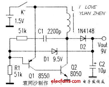
The 1.5V to 9V power supply circuit is illustrated in the diagram. This is a basic oscillation-based boost circuit. BG1, along with L1, L2, and C1, forms the oscillator. BG1 acts as the switching transistor, operating in a high-frequency oscillating mode. L1 and C1 serve as feedback components for the oscillation, while L2 functions as an energy storage winding. Additionally, the circuit includes an automatic electronic switch made from BG3. When there is no load connected to the base of BG3, no base current flows, which turns off BG3, BG2, and BG1, effectively stopping the circuit and eliminating any power consumption. This design eliminates the need for a separate power switch. When points A and B are connected to a load, BG3 turns on, which activates BG2. This allows the load to provide the base current to BG1, turning it on. Energy is drawn from the power source and stored in L2. At this moment, the collector voltage of BG1 is very low, causing D1 to be reverse-biased and cut off. The load is then powered by the residual voltage of C2. When BG1 turns off, the current through L2 cannot change abruptly, generating a higher back-EMF that is rectified by D1 and output. Once the output voltage exceeds the regulation value of D2, the base-emitter junction of BG2 becomes reverse-biased, reducing the base current of BG1 and weakening the oscillation, thus lowering the output voltage back to near the regulated level. For BG1, choose an NPN silicon transistor with low saturation voltage, such as 9013 or 8050, ensuring ICM ≥ 300mA and β ≥ 200. BG2 can be a PNP transistor like 9012 or 9015, and BG3 should be an NPN transistor like 9014. Lower leakage current is better. L1 and L2 should be wound on a high-frequency 8mm ferrite ring (from an old electronic ballast or energy-saving lamp), using 0.1mm enameled wire. L1 has 6 turns, and L2 has 36 turns. I used this circuit to power a DT890A digital multimeter. The measured working current was below 45mA for the buzzer and 20uF/2uF capacitor blocks, and less than 25mA on other ranges. When the battery voltage dropped to 0.9V, only the buzzer block showed a low battery warning, while the other ranges still functioned properly. The circuit is simple to build, stable, and cost-effective. No tuning is required—just correct wiring ensures proper operation. Most digital multimeters require a separate power switch when using a 1.5V battery instead of a 9V battery. This circuit automatically starts and stops based on the presence of the multimeter’s operating current, eliminating the need for an extra switch. Simply connect the power line to the output of the boost circuit, and the multimeter’s own switch will control the power flow. C1 serves as a positive feedback component. When Q2 turns on, the positive feedback from C1 causes Q2 to quickly enter saturation. As C1 discharges and begins to charge in reverse, the base potential of Q1 increases, reducing the base current of Q2. This leads to a continuous rise in the current through L1. When the current reaches a certain threshold, Q2 exits saturation, raising its collector voltage. This triggers the positive feedback of C1 to increase the base potential of Q1, pushing both Q1 and Q2 into cutoff. After a period of time, Q1 turns on again, and R1 and C1 recharge, lowering the base potential of Q1. The charging time of the circuit is usually much longer than the discharge time, including the waiting period for recharging. When D1 is connected, the output voltage may become too high, affecting the charging and discharging of C1. This results in shorter on-time for Q1 and Q2 and longer waiting times after discharge. As shown in the analysis, the operating frequency of this circuit depends on both R1 and C1, though it is slightly influenced by L1. The driving capability of the circuit is affected by the values of R1, L1, and the gain of Q1 and Q2. This circuit is easy to start, and the conditions for no oscillation are: R1 is relatively small. Once Q1 and Q2 turn on, C1 completes its reverse charging, and the current through Q1 reaches a minimum. If Q2 remains in saturation (due to the internal resistance of L1 limiting the collector current), it consumes a lot of power, causing the circuit to stop operating. REMOTE CONTROL SOCKET
Programming Instructions
•Press any ON switch on the Remote Control for approximately 2 seconds and the Remote Socket(s) learn the code. The LED will stop flashing top confirm the codehas been accepted. Remote Control Electrical Outlets,Remote Control Outlet,Remote Controlled Power Socket,Wireless Remote Control Outlet,Mini Wireless Remote Control Outlet,Wireless Remote Power Switch NINGBO COWELL ELECTRONICS & TECHNOLOGY CO., LTD , https://www.cowellsockets.com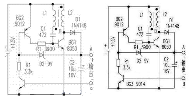
Important Safeguards
When using any electrical appliance, in order to reduce the risk of fire, electric shock and/or injury to persons, basic safety precautions should always be follow8d. including:
• The appliance is for household and indoor use only.
• Before plugging in. check that the voitage on the rating label is the same as the mains supply.
• To protect against electric shock, do not immerse any part of the product in water or other liquid.
• This socket is intended for use by competent adults only and children should be supervised at all times.
• Do not use the socket for other than its intended use.
• This socket can be used by children aged from 8 years arxl above and persons with reduced physical, sensory or mental capabilities or lack of experience and knowledge if they have been given supervision or instruction concerning use of the appliance in a safe way and understand the hazards involved. Children shall not p<ay with the appliance Cleaning and user maintenance shall M be made by children without supervision.
• Children of less than 3 years should be kept away unless continuously supervised.
Children from 3 years and less than 8 years shall only switch on/off the appliance provided that it has been placed or installed in its intended normal operating position and they have been supervision or instruction concerning use of the appliance in a safe way and understand the hazards involved. Children aged from 3 years and less than 8 years shall not plug in. regulate and clean the appliance or perform user maintenance.
• Don't use this socket in the immediate surroundings of a bath, a shower or a swimming pool.
• In case of malfunction, do not try to repair the socket yourself, it may result in a fire hazard or electric shock
Do Not Exceed Maximum a680W
Place the LR44 batteries provided into the compartment in the back of the Remote Control, please insert as sho*/m in the back of the compartment to ensure the polarity is correct.
• Plug the Remoce Socket$($)lnto the wall socket(s) and switch on the mams supply, the red LED will flash every second.
• If the LED is not flashing press & hold the manual ON/OFF button for 5 seconds until it Hashes
• Any number of Remote Sockets can be programmed to one Remote Control ON button to create multiple switching.
• To programme o<her Remote Sockets on different Remote Control ON buttons repeat the prevous steps
• If the mains supply is turned off the Remote Sockets v/ill lose their code and it wil be necessary to re-pcogramme.
Operation:
• Plug your appliance(s) into the Remote Socket(s)
• Press the programmed ON or OFF button on the Remote Control to control the Remote Socket.
♦ The Remote Sockets can also be operated manually using its ON/OFF Button Trouble shooting
If a Remote Socket does not react to the Remote Control please check the followng:
♦ Low battery in tbo Remote Control
• Distance too large between the remote control and the recerver (ensure the range distance is no more than 20 clear Metres) and free from obstacle that may reduce the distance.
• If programming has not been successful, tum the power off and back on then follow the programming steps above.
How to decode
• Press the manual ONX)FF button for 5 seconds until the red LED flashes once per
second to confirm de-coding is successful
♦ Press the ALL OFF switch on the Remote Control for more than 3 seconds, the LED
flashes once per second to confirm (decoding successful.
Voltage: 240V-/50HZ
Max power rating: 3680W max.
Remote frequency:
Remote range:
Battery Type:
433.92MHz
230 Metres
Button Cell 2x1.5V LR44 =
Please check with your local waste management service authority regarding regulations for the safe disposal of the batteries. The batteries should never be placed G municipal waste.
Use a battery d^posal facility if available
M
For eioctncal products sold within the European Community. At the end of the electrical products useful life, it should not be disposed of wth household waste. Please recycle faaMies exist. Check with your Local Authonty or retailer for recycling advice.
C€
The simplest 9v boost circuit diagram Daquan (four boost circuit schematics detailed)
The simplest 9V boost circuit diagram (1)