This article refers to the address: http://
Internally Installed Digital LED Strip puts main part of the driver IC is integrated into the commonly used 5050RGB patch lamp bead.
reducing external components, reducing the volume and reducing the production cost.
Control circuit and RGB chip is integrated into a 5050 packaged component to form a complete external control pixel.
The three primary colors of each pixel can achieve 256 levels of brightness display, serial cascade interface,
and can receive and decode data through signal lines. The color of the light is highly consistent and cost-effective.
Generally used for LED full color luminous word string, LED full color module, LED full color soft light strip hard light strip,
Led Pixel Screen, LED shaped screen and so on. It is one of the most common ribbons on the market.
Internally Installed Digital Led Strip Digital LED Strip,5050Rgb LED,LED Strip Light Waterproof,Internally Installed Digital LED Strip SHEN ZHEN SEL LIGHTING CO.,LTD , https://www.sellighting.com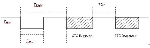
The advantage is that the circuit is integrated into the led bead, the external circuit can be omitted, and reduce the circuit design,
A Practical K-Line Diagnostic Protocol Driver Design
introduction:
With the increase of the functions of the electronic control unit of the car and the need for upgrading, the diagnostic function has become an indispensable part of the ECU . Therefore, it is necessary to thoroughly study the diagnostic protocol and its implementation. Based on ISO 14230 K line CAN bus and two diagnostic industry standard ISO15765 is widely used [1], K-line is defined by ISO9141 diagnostic communication bus, on the basis of ISO 14230 will be extended to 24V line voltage ISO9141 K and extended Diagnostic service. Compared with the CAN bus, the K- line diagnosis can meet the requirements and save costs, and it can be applied on a large scale in domestically produced vehicles. Different from the CAN bus, there is a special protocol driver. The user directly writes the application without managing the underlying communication. The K- line does not have a special protocol driver. Generally, the underlying communication management is implemented by software on the basis of the SCI module. The author is A domestic car designed a body control module with K- line diagnostic function, combined with the ISO14230 specification, first analyzes the function of the K- wire diagnostic protocol driver, then introduces the key design techniques of the protocol driver, and finally tests with CANoe .
1 protocol driver function
ISO 14230-1 defines the K- line physical layer protocol, ISO 14230-2 defines the data link layer protocol, and ISO 14230-3 defines the application layer protocol [ 2 ] . The correspondence between it and the OSI model is shown in Table 1 .
OSI model
K- line diagnostic protocol
Application layer
ISO14230-3
Presentation layer
N/A
Session layer
N/A
Transport layer
N/A
Network layer
N/A
data link layer
ISO14230-2
Physical layer
ISO14230-1
Table 1 Correspondence between ISO14230 and OSI models
The physical layer defines the correspondence between logical bits and physical levels, and defines the rise and fall times of the signal bits. The data link layer protocol defines the K- line data format, diagnostic message format, timing parameters, and communication error determination. The processing mechanism, the application layer protocol defines a request / response based diagnostic process and various diagnostic services. As the ECU node to be diagnosed, the main functions of the K- line protocol driver are:
1. Encapsulate and send, receive, and parse diagnostic messages, and fill / extract SIDs and data according to the message format;
2. Establish diagnostic communication with the diagnostic instrument through the initialization process;
3. Maintain correct inter-frame timing, inter-byte timing, detection of timing errors of diagnostic instrument messages and other communication errors;
4. Manage the diagnostic session by returning the corresponding diagnostic response according to the diagnostic request of the diagnostic device and the current state of the ECU ;
The following describes the principle and implementation of the K- line diagnostic protocol driver in combination with the protocol analysis of the data link layer and its data structure and driver design.
2 protocol driver design
The K- line is based on an asynchronous serial communication interface. The SCI serial data link format of 8N1 format is used in the underlying transmission: 8 data bits + 1 stop bit, no parity, since the K line is a single root on the physical layer. The line also triggers the reception interrupt when transmitting, so the transmission and reception analysis of the K- line message is unified in the SCI reception interrupt processing function in the form of a state machine [ 3 ] . The following describes the implementation of the data link layer from three aspects: packet transmission and reception, resolution, initialization, and timing management.
2.1 Packet Transceiver and Analysis
The structure of the K- line diagnostic message is shown in Table 2 :
Message header
Data field
Checksum
Fmt
Tgt
Src
Len
Sid
Data
CS
Up to 4 bytes
Up to 63 bytes or 255 bytes
1 byte
Table 2 K- line diagnostic message structure
The K- line message consists of a message header, a data field, and a checksum. Format byte header comprises Fmt, the Tgt destination address, source address and optionally the additional length information Src Len, Fmt target address form (physical address / function address), when the packet header does not contain an optional field Len Specifies the length of the data field; the data field includes the service identifier Sid and the data Data , the length of which is determined by Fmt and Len ; CS is a single-byte checksum. The design message structure is as follows:
Typedef struct
{
K_state state;
Uchar fmt;
Uchar tgt_addr;
Uchar src_addr;
Uchar datalen;
Uchar sid;
Uchar *data;
Uchar checksum;
Uchar msgdatalen;
Uchar done;
}k_msg;
Typedef enum{
k_FMT=0,
k_TGTADDR,
k_SRCADDR,
k_DATALEN,
k_SID,
k_DATA,
k_CS
}k_state;
The member variable state indicates which component of the message the current K- line communication data is, msgdatalen is used for the statistics of the number of bytes of the data field, done indicates whether the message is sent or received, and other member variables and the packet structure component are A correspondence.
Void k_ifc_rx(void)
{
K_u8 ch, SciSr1;
SciSr1=Kline_periph[SCISR1];
Ch=Kline_periph[SCIDRL];
TimerStop(k_TP4);
Switch(k_curmsg.state){
Case k_FMT:
If(k_REP==k_drvhandle.mode){
If(ch==k_curmsg.fmt){
K_curmsg.state=k_TGTADDR;
k_SendChar(k_curmsg.tgt_addr);
}
}else{
K_curmsg.state=k_TGTADDR;
K_curmsg.fmt=ch;
}
Break;
Case k_TGTADDR:
...
Break;
Case k_SRCADDR:
...
Break;
Case k_DATALEN:
If(k_REP==k_drvhandle.mode){
If(ch==k_curmsg.datalen){
K_curmsg.msgdatalen=0;
K_curmsg.state=k_SID;
k_SendChar(k_curmsg.sid);
}
}else{
K_curmsg.msgdatalen=0;
K_curmsg.datalen=ch;
Free(k_curmsg.data);
K_curmsg.data=malloc(k_curmsg.datalen);
K_curmsg.state=k_SID;
}
Break;
Case k_SID:
If(k_REP==k_drvhandle.mode){
If(ch==k_curmsg.sid){
K_curmsg.msgdatalen++;
If(k_curmsg.msgdatalen==k_curmsg.datalen){
K_curmsg.state=k_CS;
k_SendChar(k_curmsg.checksu);
}else{
K_curmsg.state=k_DATA;
k_SendChar(k_curmsg.data[0]);
}
}
}else{
K_curmsg.sid=ch;
K_curmsg.msgdatalen++;
If(k_curmsg.datalen==k_curmsg.msgdatalen){
K_curmsg.state=k_CS;
}else{
K_curmsg.state=k_DATA;
}
}
Break;
Case k_DATA:
...
Break;
Case k_CS:
K_curmsg.state=k_FMT;
If(k_REP==k_drvhandle.mode){
If(ch==k_curmsg.checksum){
K_curmsg.done=1;
}
}else{
K_curmsg.checksum=ch;
K_curmsg.done=1;
}
Break;
} if((k_REQ==k_drvhandle.mode)&&(k_FMT!=k_curmsg.state)){
TimerStart(k_REP_P4MS, k_TP4, 0, 1);
}
}
2.2 initialization
Before starting diagnostic services, diagnostic equipment necessary to initialize the ECU, ECU get support packet header format and timing parameters in response to the ECU, to establish the diagnosis communication [4]. The initialization process is shown in Figure 1. The diagnostic device sends a 25ms '0' , 25ms'1' WuP (WakeUp Pattern) , and then sends an STC (StartCommunication) Request . The ECU detects the WuP and receives the correct STC Request and returns to the STC. Response, the packet by the Data field "key (Key Word)" composed of two bytes, specifies the packet header information and timing parameters supported by the ECU, such as a designated Key Word means that the packet 0x8fea The header uses the additional length information Len to indicate the length of the data field, while using the default timing parameters.
Figure 1 initialization process
Before the initialization, the K line is in the idle state, the ECU disables the SCI function and enables the RXD pin of the SCI to be in the IO mode, and the duration of the IO low level of the RXD pin is counted by the timer when the falling edge is detected, and the rising edge is detected. IO high statistical RXD pin duration starts, it is determined whether a valid WUP; SCI baud rate may be set to 200bps, determines whether the data can be received 0xf0 (0xf0 expressed as 0 on the bus 5, 5 1 ), after detecting the correct WuP , enable the SCI function, set the baud rate to 10400bps , wait for the STC Request sent by the diagnostic device , return to the STC Response after receiving the request, and establish a diagnostic communication.
2.3 timing management
ISO14230 defines four timing parameters to manage inter-byte timing and inter-message timing. The diagnostic instrument and ECU need to comply with these timing constraints to ensure normal diagnostic communication. Table 2 gives the meaning and value of these four timing parameters. Interval.
Parameter variable
description
Minimum value (ms)
Maximum value (ms)
P1
Inter-byte time interval for ECU response
0
20
P2
The time interval between the diagnostic request and the ECU response, or the time interval between the two ECU responses
25
50
P3
Time interval between ECU response and diagnostics request
55
5000
P4
Inter-byte time interval requested by the diagnostic
0
20
Table 2 timing parameters
P1 and P4 are the inter-byte timings in the message, and P2 and P3 are the inter-message timings. The diagnostic device needs to send a diagnostic request within P3 after the initialization is completed or after receiving the diagnostic response. Otherwise, the ECU exits the diagnostic session, disconnects the diagnostic communication, and the K- line protocol driver restarts, waiting for the diagnostic device to issue the next WuP and STC Request . After receiving the diagnostic request, the ECU needs to return the diagnostic response within P2 time. P2 is controlled by the ECU , usually with a fixed value of 25ms . When the Fmt field in the diagnostic request message specifies the target address as the "function address", P2 The value needs to be generated by a random number generator, because for a functionally addressed diagnostic request, multiple ECUs may return a response. If a fixed P2 parameter is used, it may occur because multiple ECUs compete for the bus. Bus conflict problem, P2 uses random number, ECU will not return response at the same time, thus avoiding bus competition.
3 protocol driver test
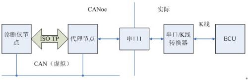
The protocol driver is tested on Vector 's CANoe software and hardware platform. When K -based KWP2000 service testing is performed, the KWP2000.dll and KLineCPL.dll modules are added to the CANoe simulation environment, the CANoe analog diagnostics node, and a proxy node is used. The message forwarding between the CAN network and the K line is realized. At this time, CANoe uses the serial port of the computer and is connected to the ECU through the serial port /K line converter. The diagnostic implementation framework is shown in FIG. 2 .
Figure 2 K- line diagnostic framework
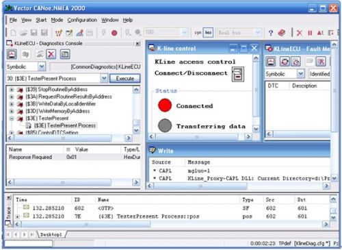
Different from the CAN bus diagnosis, the K- line diagnosis requires the diagnostic instrument to establish diagnostic communication through the initialization process and the ECU. The establishment of the diagnostic communication is shown in Figure 3 . After the diagnosis communication is established, the diagnosis service can be performed like the CAN diagnosis. There are many papers in this area, and will not be described here.
Figure 3 establishes diagnostic communication
Conclusion
Implementation of this K-wire protocol driver module rigorously tested, the K-line diagnostics can be efficiently completed, to achieve the desired design performance and stability requirements. The driver is independent of the processor and operating system, has good versatility and flexibility, can be easily integrated into the application, has high practical value and reference.