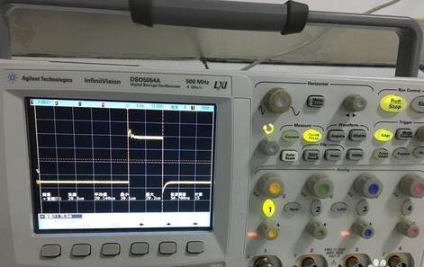
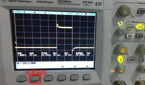
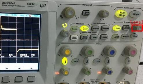
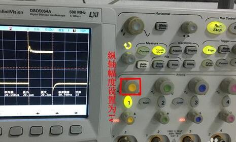
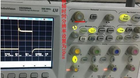
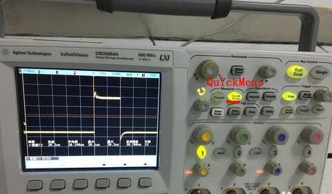
The pulse signal is a kind of discrete signal with many shapes. Compared with common analog signal (such as sine wave), the waveforms are not continuous on the time axis (there are obvious intervals between the waveform and waveform), but they have a certain periodicity. Is its characteristics. The most common pulse wave is a rectangular wave (that is, a square wave). Pulse signals can be used to represent information, and can also be used as a carrier wave, such as pulse code modulation (PCM), pulse width modulation (PWM), etc. in pulse modulation, and also as clock signals for various digital circuits and high-performance chips. . The so-called pulse signal in the plane coordinates is a curve with numerous breakpoints, that is to say, in the periodical places, the limits of the points do not exist, such as the sawtooth wave, but also the signal of the digital circuit used in the computer, 0,1 . Pulse signals, which are signals such as pulse beats, are relative to direct current and intermittent signals. If the flow of water is used, the direct current is to keep the faucet open and the pulse is constantly turning on the faucet to form a water pulse. You turn on the light with the handle, this is the direct current. When you keep on and off, the pulse is formed. The speed of the switch is the level of the pulse frequency. If it is simple to detect the presence or absence of a pulse signal, or if only an empirical value and an inaccurate value are used, the frequency range of the multimeter can be used. The pulse signal basically has the similar AC pulse as the positive and negative fixed exchange signals and the fixed positive pulse signals and the negative pulse signals. One is to use AC gear, and one is to use DC gear. The measured value is inaccurate. A better watch will have multiple HZ files, but for a tiny pulse signal, there is no way to measure the signal voltage. It is the digital multimeter that cannot measure the voltage of the pulse signal, then need the oscillograph or special instrument. Digital meters rely on sampling, and this sampling time and the pulse you are testing are very likely to be measured RMS is not the maximum value. Unless you can adjust the sampling frequency of the digital meter to adjust to the pulse frequency you are testing, at this time, your meter indicator will display the value, then the pulse voltage. Then follow Xiaobian to learn more about how the oscilloscope measures the pulse signal. Take the method of oscilloscope to measure the pulse width of 1pps pulse signal as an example. The general steps are: select measurement channel 1, connect 1pps pulse signal, set impedance, trigger level, Analog amplitude (vertical axis), Horizontal time resolution (horizontal Axis) and other parameters are then measured by QuickMeas with the positive pulse width of the 1pps pulse signal. 1. Turn on the oscilloscope and connect the 1pps pulse signal cable to measurement channel 1. Light up the oval button of measurement channel 1. Click AutoScale. The impedance, trigger level, analog vertical axis amplitude, horizontal axis time resolution, etc. Parameter settings. 2. Click the second button at the bottom of the screen to set the impedance to 50Ω. 3. Set the trigger level to 700mV with the Level knob in the Trigger area. 4. Set the vertical axis amplitude to 1v by using the first knob in the Analog field. 5. Use the first knob in the Horizontal area to set the horizontal axis time resolution to 10us. The observation screen is displayed as a square wave. 6. Click QuickMeas and select “Positive Pulse Width†to read the measured value (average). As shown in the figure below, the positive pulse width measurement (average) of the 1pps pulse signal is: 20.140us. Measurement considerations 1. Measure the output impedance of the 10MHz frequency signal. The parameters are set as follows: impedance 50Ω/1MΩ, trigger level 0v, and Analog longitudinal axis amplitude 1V. 2. Measure the positive pulse width of the 1pps pulse signal. The parameters are set as follows: impedance 50Ω, trigger level 700mV, Analog longitudinal axis amplitude 1V, Horizontal axis time resolution 10us. 3. Measure the period of the 1pps pulse signal. The parameters are set as follows: impedance 50Ω, trigger level 700mV, Analog longitudinal axis amplitude 1V, horizontal axis time resolution 1s. Fork Type Connecting Terminals Fork Type Connecting Terminals,Terminals,Connecting Terminals Taixing Longyi Terminals Co.,Ltd. , https://www.longyicopperterminals.com
Can a Multimeter Measure Pulse Signals? How to Measure Pulse Signals (Step Tutorial)
Pulse signal introduction