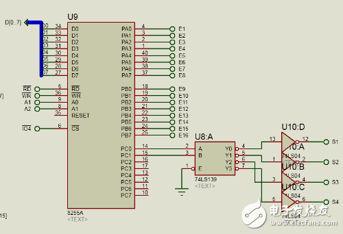
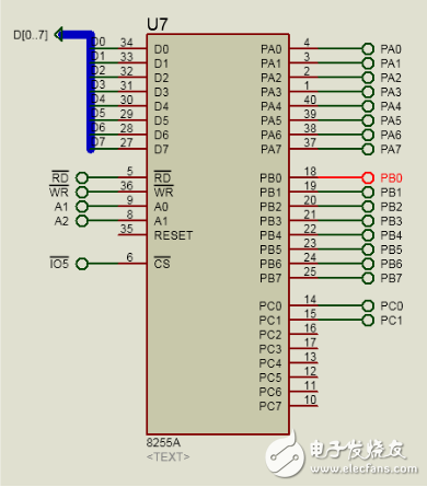
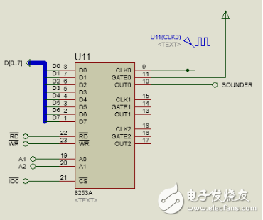
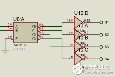
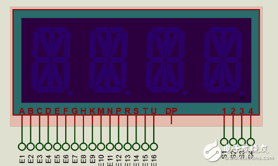
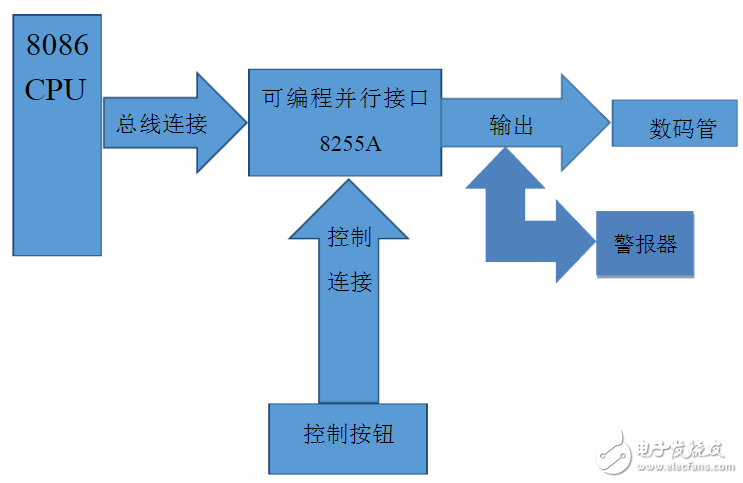
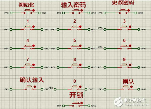
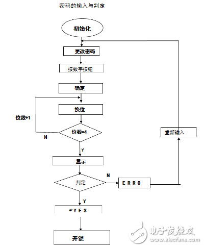
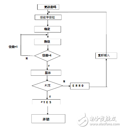
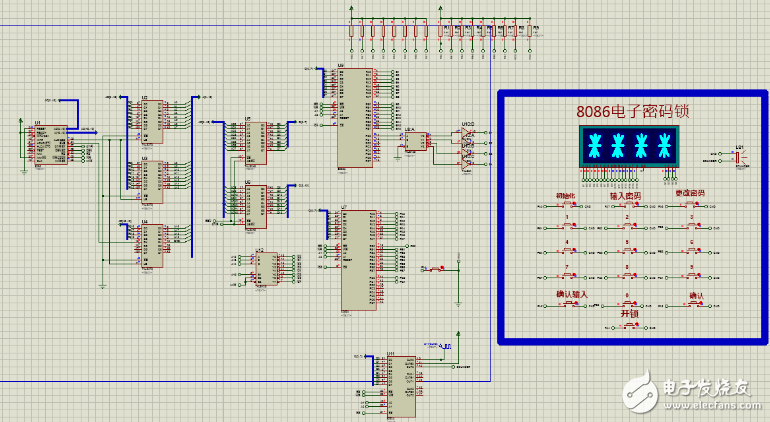
The electronic code lock is an electronic product that controls the circuit or the chip by password input, thereby controlling the closing of the mechanical switch and completing the task of unlocking and locking. It has many types, simple circuit products, and chip-based products with high cost performance. The widely used electronic code lock is implemented by programming with the chip as the core. (1) At the beginning of execution, each digit of the digital tube displays “meterâ€, and the first digit of the input digital password tube displays “meterâ€, and clicks the number key to select the number; (2), press the "confirm" button and jump to the second number, the operation is the same as the first step; (3) When the four passwords are selected, press the “Confirm Input†button to display the entered password; (4), press the "unlock" button, if the password is correct, and *YES is displayed, the password lock is turned on; (5), press the "unlock" button, if the password is wrong, the display ERRO, the password lock can not be opened, press the "enter password" button, you can re-enter the password. (1) When *YES is displayed, press the "Change Password" button and enter the new four-digit password; (2), press the "confirm input" button to display the new password, press the "confirm" button to set a new password. If you enter an incorrect password more than 5 times, the alarm will sound automatically and the alarm will be released only if you enter the correct password again. First piece 8255 The ABC port is defined as the output state, and the AB port controls the input port of the digital tube, corresponding to the corresponding segment code table, to display. The PC0 and PC1 of the C port pass through the 2-4 decoder to activate the digital tube 1, 2, 3, 4 channels, and adopt the 00, 01, 10, 11 and cyclic output mode to activate the digital tube channel cycle. Dynamic display. Second piece 8255 The definitions A, B, and C are all input states, corresponding to the corresponding button states, corresponding to the corresponding programs, to achieve the corresponding functions. Use 0 channel, mode 3, divide the input signal at all times. When the number of input passwords is greater than 5 times, initialize 8253 and sound an alarm. When the password is entered correctly, 1 channel is activated and the alarm prompts the sound. Because the 8086 runs too fast, the digital tube dynamic display shows incomplete display. Therefore, PC0 and PC1 output after 2-4 decoder, then activate the digital tube to play a buffer role. 16-digit digital tube digital tube, controlled by 16 pins, active low, where AH controls outer ring 0, KM controls internal * S1-s4 is channel control and active high. In this experimental design, the hardware part involves the 8086CPU, programmable parallel interface 8255A, and with the 74LS373 latch, 74LS245 buffer, 74LS138 decoder and other basic components, the realization of the electronic lock. 8255A: As shown in the figure, the D0~D7 ports of the 8255A are connected to the CPU data lines ADO~AD7. The CPU reads, writes and selects the 8255A through the chip select, read and write signal interfaces of the control line. A0-A7 of the peripheral interface side is connected to the A0-A7 port of 245, and the peripheral information is transmitted to 245, and various functions such as password input, password determination, and password modification are input. As shown in the figure, the PA0-PA7 port of port A is connected to the digital tube through the latch for the outer ring display, and the PB0-PB7 port of port B is connected to the digital tube through the 74LS373 latch for the internal "meter" character. display. Enter the control word for the 8255A input port: void fun82531() { __asm { Mov dx, 0x8006 Mov al, 0x37 Out dx, al } Outp(GATE0,0x02); Outp(GATE0,0x00); } Void fun82532() { __asm { Mov dx, 0x8006 Mov al, 0x77 Out dx, al } Outp(GATE0,0x99); outp(GATE0,0x99); } The whole process is mainly to scan whether there is a key information input, and compare the obtained information with the lamp number to determine the lamp to be selected to input the number. When the current lamp number is selected, it automatically jumps to the next lamp until all four digits have been selected. After the four-digit password is selected, the four selected digits are displayed, and then the correctness of the password is detected. The 8255A reads the command through ports A, B, and C. According to the detection result, if the password is correct, the output code displays *YES, and the error displays ERRO. After changing the password and typing the “Change Password†control word, the process is the same as entering the password. First select the lamp, skip the selected number and skip to the next one, until all four digits are selected, then type the “confirm change†command. The password is changed successfully. System implementation As shown in the figure, the Proteus simulation diagram of this experiment, the whole experiment is shared to 8086CPU one, 74LS245 one, programmable parallel interface 8255A, 74LS273 latch three, 74LS138 decoder one, digital tube one, NAND gate two Eight, eight switches, eight resistors. UV Film,UV Screen Protector,UV Curing Screen Protector Shenzhen Jianjiantong Technology Co., Ltd. , https://www.hydrogelprotectivefilm.com