Today I will introduce to you a national invention authorized patent-a thermal porous gas flowmeter applied to uneven flow field. The patent was applied by Nanjing Bowo Technology Development Co., Ltd., and the authorization announcement was obtained on May 4, 2018. The invention relates to a thermal porous gas flowmeter applied to an uneven flow field, and belongs to the technical field of gas flow measurement. Gas flow is an important parameter for industrial production process and scientific experiment measurement. Flowmeter is a tool for measuring and testing gas flow. Gas flow measurement is an important part of energy measurement, and plays an important role in ensuring product quality, improving production efficiency, saving energy, and promoting the development of science and technology. Gas flow measurement is very dependent on the application conditions, and the influencing factors include the type of gas, flow conditions, and field application conditions. In the laboratory, the flowmeter can obtain extremely high accuracy, but once the gas conditions or environmental conditions have changed greatly in the field application, not only the accuracy cannot be guaranteed, but even normal use is not possible. For example, there are many gas flow measurements in large-diameter pipelines. The problem is that the gas velocity distribution in large-diameter pipelines is uneven, and single-point measurement is not representative, resulting in a large deviation between the measured value and the actual value. Common gas flowmeters are classified according to principles, and can be roughly divided into differential pressure flowmeters, thermal flowmeters, turbine flowmeters, vortex flowmeters, and ultrasonic flowmeters. Among them, the differential pressure flowmeter is the most widely used, and there are many specific structural types. The orifice plate flowmeter is a common type of differential pressure flowmeter. It uses the static pressure difference generated when the fluid flows through the orifice plate as a single measurement signal, which is led out by the pressure tube and passed through the differential pressure transmitter. Converted into electric signal, and then converted into corresponding flow value display through configuration. The orifice plate is generally divided into a single-hole design and a porous design. The porous orifice plate has relatively low requirements for the uniformity of the measured gas, that is, the requirements for the straight pipe section upstream of the measurement section are shorter. The porous plate gas flowmeter is playing an increasingly important role in industrial production due to its strong adaptability to uneven flow fields. The porous plate gas flowmeter is designed based on the throttling principle. To ensure its accuracy, it is necessary to design a sufficient differential pressure, but it is not allowed under certain industrial process requirements. At the same time, the throttling loss is too large and the operation is not economical. In addition, The primary differential pressure signal provided by the porous plate gas flowmeter is proportional to the square of the flow rate. When the flow rate decreases, the primary differential pressure signal is greatly reduced, so it is difficult to balance the wide range ratio design and low pressure loss design. Differential pressure flowmeters including porous plate gas flowmeters must lead the measured primary differential pressure signal to the differential pressure transmitter through the pressure tube. When there are condensation, crystallization and other phenomena in the measured gas components , It is easy to cause blockage of the impulse tube, which in turn causes the flowmeter to fail to operate normally. Although the traditional multi-plate gas flowmeter has advantages in the field of gas flow measurement in a non-uniform flow field, it is not suitable for all working conditions. The process requirements as mentioned above do not allow excessive throttling loss and measurement gas Some components have condensation, crystallization and other phenomena. In response to these measurement difficulties, the thermal gas flowmeter can be partially or even completely overcome, but it does not have a good adaptability to the uneven flow field. The thermal gas flowmeter is designed based on the principle of thermal diffusion. Its typical sensing element includes two thermal resistances, one is a speed sensor, and the other is a temperature sensor used to automatically compensate for changes in gas temperature. When the two thermal resistances are placed in the measured gas, the speed sensor is heated to a constant temperature above the ambient temperature, and the corresponding gas flow is calculated by its heat transfer amount. As the gas flow rate increases, the amount of heat taken away increases. In order to maintain the flow rate sensor at a constant temperature, the working current through the sensor must be increased. The increased current is proportional to the gas flow rate. The flow resistance loss caused by the thermal gas flow meter is small, and the range is relatively wide, which can measure the gas flow rate with a low flow rate. In addition, the thermal gas flowmeter can measure the gas flow rate up to 500 ℃, and the core components generated by the electrical signal are placed in the hot gas, which can avoid the condensation and crystallization of the differential pressure flowmeter under certain application conditions. problem. In summary, the accurate and reliable measurement of gas flow can only be obtained by targeted design according to the application conditions. Various gas flow measurement technologies have their applicable environments, which have their advantages and disadvantages. In order to solve the problems in the existing technology, overcome the difficulties of low flow rate and uneven flow field faced by gas flow measurement in large-diameter pipelines, and the possible difficulties of condensation and crystallization of some components in the measurement gas when cold. The invention provides a thermal porous plate gas flowmeter applied to an uneven flow field. In order to solve the above technical problems, the technical scheme adopted by the present invention is as follows: a thermal porous plate gas flowmeter applied to an uneven flow field, including an outer sleeve, an inner sleeve, a first porous plate, a temperature sensor, and a speed Sensor and signal transmitter; the first porous plate is set in the outer sleeve, and the plane of the first porous plate is perpendicular to the axial direction of the outer sleeve; the inner sleeve is set in the outer sleeve, one end of the inner sleeve is the upper port, and the other One end is the lower port, and the lower port of the inner sleeve passes through the first porous plate; the temperature sensor and the speed sensor are installed in the inner sleeve, and both the temperature sensor and the speed sensor are connected to the signal transmitter. The present invention is applied to a thermal porous plate gas flow meter with an uneven flow field, and has a sleeve structure. Preferably, the plane where the first porous plate is located is parallel to the gas flow cross section, and the length direction of the inner sleeve is parallel to the gas flow direction. The inner sleeve has two ends, which are respectively defined as an upper port and a lower port. The upper port and the lower port of the inner sleeve are located upstream and downstream of the first porous plate; the lower port of the inner sleeve passes through the first porous plate , That is, the inner sleeve passes through the first porous plate, and the first porous plate is located between the upper port and the lower port of the inner sleeve. The upstream and downstream of the present invention refer to the upstream and downstream of the measured gas along the flow direction of the outer casing. The direction from upstream to downstream is the same as the direction from upper port to lower port. Using the above technical solution, the measurement gas circulates in the outer casing, and the measurement gas flows through the first porous plate, causing throttling loss, and a static pressure difference between the upstream and downstream, which drives the gas velocity in the inner casing to increase and the velocity sensor to obtain a greater The signal is measured once, and the signal strength reflects the average flow rate of the entire flow section of the outer sleeve. The flowmeter of the invention is calibrated by a laboratory standard flowmeter to obtain the conversion relationship between the primary measurement signal of the speed sensor and the temperature sensor and the gas flow rate. In the signal transmitter, the primary signal is calculated and transmitted or directly displayed. In order to improve the accuracy of the measurement, the temperature sensor and the speed sensor are installed at the lower port in the inner casing; the signal transmitter is located outside the outer casing. In order to further improve the accuracy of the measurement, the ratio of the length of the inner sleeve upstream of the speed sensor to the diameter or equivalent diameter is greater than 10. The inner casing flow section is less than 1/10 of the outer casing flow section. Therefore, it is easy to ensure that the ratio of the length of the inner sleeve upstream to the speed sensor to the diameter or equivalent diameter is greater than 10, thereby improving the accuracy of the speed sensor's one-time measurement signal. The ratio of the length of the inner casing upstream to the speed sensor to the diameter or equivalent diameter is greater than 15. In order to improve the accuracy of the flowmeter measurement of the present invention, the upper port of the inner sleeve is provided with a streamlined or conical end cap, and the inner sleeve connected to the end cap is provided with more than one air inlet. In order to enhance the stability of the structure, the thermal porous plate gas flow meter applied to the uneven flow field also includes a second porous plate, which is located downstream of the first porous plate and The plates are arranged in parallel; the lower port of the inner sleeve simultaneously passes through the first and second orifice plates. In order to improve the accuracy of flow measurement, the distance between the second porous plate and the lower port of the inner sleeve is greater than 5 times the diameter or equivalent diameter of the inner sleeve. The number of through holes provided on the first porous plate and the second porous plate is greater than 10, and are evenly arranged along the circumferential direction. Both the outer casing and the inner casing are round pipes, which are arranged coaxially. The technologies not mentioned in the present invention refer to the prior art. The invention is applied to a thermal porous gas flowmeter with an uneven flow field, and is particularly suitable for gas flow measurement of a large diameter pipeline with an uneven flow field above DN100. It has high sensitivity, high accuracy, wide range ratio, and low throttling loss. Obvious advantages, and at the same time, it can also guarantee the entire high temperature measurement. It can directly transmit electrical signals from the high temperature gas to the external low temperature signal transmitter. It can also condense and crystallize when some components in the measured gas encounter cold. Be applicable. Stylus Pen Tip,Stylus Pencil Tip,Carbon Fiber Pen Tip,Carbon Fiber Stylus Pen Tip Shenzhen Ruidian Technology CO., Ltd , https://www.szwisonen.com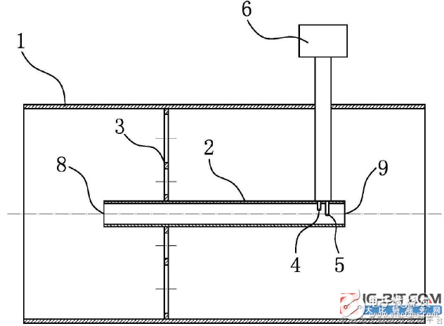
The figure is a front view of the structural features of the present invention