This article introduces a lightning protection design method that transforms the transient signals experienced by components during an instantaneous lightning strike test into reference transients as specified in component datasheets. This approach simplifies the selection of suitable components and eliminates the need for trial and error during the design phase, making the process more efficient and reliable. Additionally, we describe a technique to determine the minimum wire width required to withstand transient currents. A free graphical user interface (GUI) is introduced, which allows users to perform all calculations outlined in reference [1] and generate output results. These results can then be compared with component datasheets to ensure proper selection and ultimately lead to the design of a highly robust lightning protection circuit. To reduce aircraft weight and fuel consumption, manufacturers are increasingly using carbon composite materials instead of aluminum for fuselages. However, this shift has unintended consequences—increasing the indirect impact of lightning strikes on avionics systems. More intense transient signals now require stronger protection at the avionics interface. Yet, due to space constraints, manufacturers and suppliers aim to maintain the same equipment size, necessitating careful design of additional lightning protection circuits to use the smallest possible components. Component datasheets typically provide ratings based on standard reference transients, which may not match the actual lightning transients encountered in aircraft environments. As a result, engineers often rely on experience or select the largest available components that fit on a PCB. Wire widths were traditionally determined using IPC guidelines, but these were developed for continuous current rather than transient conditions, leading to unnecessarily wide traces. After initial design, prototypes are built and tested, followed by analysis to confirm if the selected components and wire widths are adequate. This “trial and error†process is time-consuming and resource-intensive. Fortunately, the GUI discussed in this article can streamline the process, helping designers avoid unnecessary delays and optimize their designs from the start. Chapter 22 of Reference [2] outlines the lightning impulse test transients required by the FAA for indirect lightning strike testing. Waveform 4 (WF4), shown in Figure 1, represents the transient signal used for metal aircraft. In contrast, Waveform 5A (WF5A), depicted in Figure 2, is designed for synthetic material aircraft. WF5A includes parameters such as open-circuit voltage (VOC) and short-circuit current (ISC), which help calibrate the source impedance of the test signal generator. Figure 1: Waveforms mentioned in Chapter 22 of Reference [2]. Figure 2: WF5A mentioned in Chapter 22 of Reference [2]. To determine the test level for avionics, the instantaneous lightning strike signal must be applied to the fuselage or a simulated version. Reference [3] outlines how transient signals are applied to different zones of the fuselage, as defined in literature [4]. Each zone produces specific voltage values, and for avionics connected via cables, the sum of voltages across multiple zones is calculated and doubled for each signal line. When applying the process described in [3], the lightning strike current for avionics testing has the same rise time and pulse width as WF4. However, synthetic material fuselages significantly distort this signal, while metal fuselages cause minimal distortion. As a result, WF5A has a longer duration than WF4. Additionally, composite fuselages transfer more energy from the lightning strike to the avionics. To simulate this, WF5A has a source impedance of 1 Ω, compared to 5 Ω for WF4. The distortion caused by the fuselage is due to the diffusion of the composite material and the structural voltage drop (current × resistance) coupling. Figure 3 provides a simplified visual representation of these couplings. Avionics systems, such as radios and antennas, are interconnected. The coupling effect between them can be modeled as resistors, inductors, and capacitors. The resistor represents the structured voltage drop, while the reactance accounts for the diffusion coupling. Together, these effects extend the waveform’s duration. Because WF5A has a longer duration and lower source impedance, it delivers more energy to the avionics, increasing the challenge for protection circuits. OREMA offers a high-quality dual purpose AGM Battery, a rechargeable lead-acid battery that is particularly suitable for Marine and camping vehicles. The dual purpose battery can be used not only as a starter, but also to power gear such as trolling motors. Using pure non-alloying lead materials and the most advanced plate design in the industry, OREMA batteries charge faster and last longer than traditional alloy AGM batteries, ensuring you're always ready for activities like weekend fishing. Dual Purpose Battery, dual purpose marine battery, dual purpose rv battery, dual purpose battery for truck, Dual Purpose AGM Battery OREMA POWER CO., LTD. , https://www.oremapower.com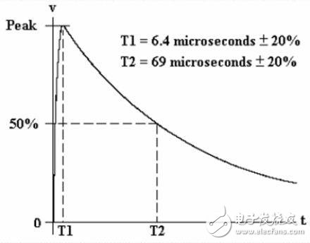
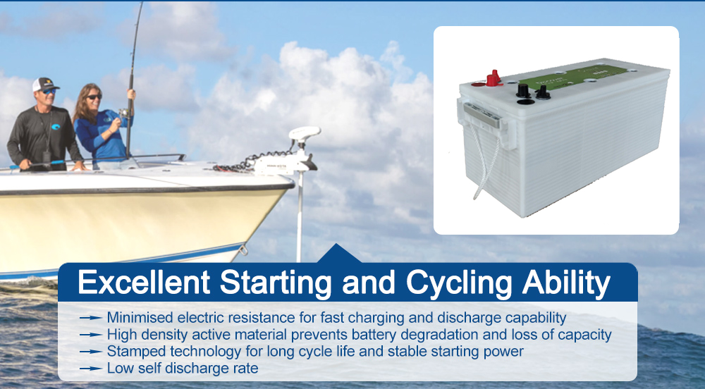
OREMA batteries are known for their excellent sustained performance and total energy output, making them particularly suitable for powering your trawling motors and other Marine accessories for extended periods of time. The battery is designed with deep recycling in mind, using thick plate technology that allows the battery to be continuously discharged and charged and discharged multiple times, ensuring reliability at sea or outdoors.
Whether sailing in the summer sea breeze or camping outdoors in early April, the OREMA battery provides lasting power and makes your journey more secure. This battery runs quietly, allowing you to focus more on enjoying nature. With OREMA proven Marine/RV power solutions, you can rest assured to enjoy the time with your family close to nature, and OREMA batteries provide you with stable and reliable power support anytime and anywhere.
Features of OREMA Dual Purpose Marine Battery:
1. Ideal for boaters, this battery provides efficient start-up capability and deep cycle power, making it ideal for use in environments where start-up power and reliable power are in high demand.
2. The battery is equipped with a special shock-proof AGM separator, which is effective against vibration and damage, which usually shorten the battery life. Its anti-vibration performance is 20 times that of ordinary flooded batteries, providing excellent shock wave protection.
3. The design pays more attention to durability, so that the battery can withstand the wear and tear during long-term recycling and extend its service life.
4. The battery has excellent electrolyte retention capability to prevent leakage of dry and acidic substances, enhancing safety.
5. In terms of safety, this battery adopts spill-free design to effectively prevent acid leakage, making installation and transportation safer.
6. The application of low current resistance separator improves the current flow, thus speeding up the battery start-up speed and increasing the efficiency.
Applications of OREMA Dual Purpose RV Battery:
Trailer
Marine
Truck
RV
Trolling motor
For all kinds of Vehicles start-stop application, and power supply application
Join the ranks of satisfied adventurers who trust OREMA Dual Purpose AGM Battery for their journeys. With OREMA Battery, power your adventures with confidence and enjoy the peace of mind that comes with unmatched performance and reliability.