This article presents a lightning protection design methodology that transforms the transient signals experienced by components during an instantaneous lightning strike test into reference transients as specified in component datasheets. This approach simplifies component selection and eliminates the need for trial and error during the design phase, ensuring better performance and reliability. Additionally, we introduce a technique to calculate the minimum wire width required to withstand transient currents. A free graphical user interface (GUI) is also described, which allows users to perform all calculations outlined in reference [1] and generate output for comparison with component datasheets. This enables engineers to select suitable components and design a highly robust lightning protection circuit efficiently. As aircraft manufacturers aim to reduce weight and improve fuel efficiency, they are increasingly using carbon composite materials instead of aluminum for fuselage construction. However, this shift has unintended consequences: it increases the indirect impact of lightning strikes on avionics systems. The resulting more severe transient signals demand stronger transient protection at the avionics interface. Yet, due to space constraints, larger components are not always feasible. Therefore, additional lightning protection circuits must be carefully designed to accommodate the smallest possible component sizes without compromising safety. Component datasheets typically provide ratings based on reference transient signals, which may differ from the actual lightning-induced transients encountered in aircraft environments. Traditional design approaches often rely on experience or the use of the largest available components that fit on a PCB. Wire widths were historically determined using IPC guidelines, which were developed for continuous current rather than transient conditions. As a result, wires are often unnecessarily wide, leading to inefficiencies in both material usage and design flexibility. After initial design, prototypes are built and tested, and results are analyzed to determine if the selected components and wire widths are adequate. This iterative “trial and error†process can be time-consuming and resource-intensive. By using the GUI introduced in this article, these delays can be significantly reduced, streamlining the design workflow and improving overall efficiency. Chapter 22 of Reference [2] outlines the lightning impulse test transients required by the Federal Aviation Administration (FAA) for indirect lightning strike testing. Waveform 4 (WF4), shown in Figure 1, represents an instantaneous test signal for metal aircraft. In contrast, Waveform 5A (WF5A), depicted in Figure 2, is used for synthetic material aircraft. WF5A includes parameters such as open-circuit voltage (VOC) and short-circuit current (ISC), which help calibrate the source impedance of the transient signal generator used in testing. To determine the test level for avionics, the instantaneous lightning strike signal must be applied to the fuselage or a simulation of it. Reference [3] details how transient signals are applied to different zones of the fuselage, as defined in literature [4]. These tests produce voltage values for each zone, and for avionics connected via cables, the sum of voltages across all zones must be calculated and doubled for each signal line. When applying the process from [3] to determine the lightning strike current for avionics testing, the waveform retains the same rise time and pulse width as WF4. However, synthetic material fuselages can severely distort the transient signal, unlike metal structures, which cause negligible distortion. As a result, WF5A has a longer duration than WF4. Moreover, composite fuselages transfer more energy from the lightning strike to the avionics. To simulate this, WF5A has a source impedance of 1 Ω, compared to 5 Ω for WF4. The distortion caused by the composite fuselage arises from the diffusion of the material and the structural voltage drop (current × resistance) coupling. Figure 3 provides a simplified visual representation of these couplings. Avionics systems, such as radios and antennas, are interconnected through various signal lines. The interaction between these systems and the fuselage's structure plays a critical role in how lightning transients are coupled into the avionics. When analyzing structural voltage drop and diffusion coupling, the fuselage can be modeled as a resistor through which lightning current flows. Avionics connected via signal lines are effectively in parallel with this resistor. Cables connecting avionics can be represented as inductors and capacitors. The current through the resistor represents the structured voltage drop coupling, while the reactance represents the diffusion coupling. Together, these effects extend the waveform’s duration. Since WF5A has a longer duration and lower source impedance, it delivers more energy to the avionics, even at the same test level. High Rate Battery Solutions by OREMA: Powering the Future High Rate Battery,high rate discharge battery,High Rate Battery pack,high rate current battery,12V high rate batteries OREMA POWER CO., LTD. , https://www.oremapower.com
High Rate Discharge Battery Excellence:
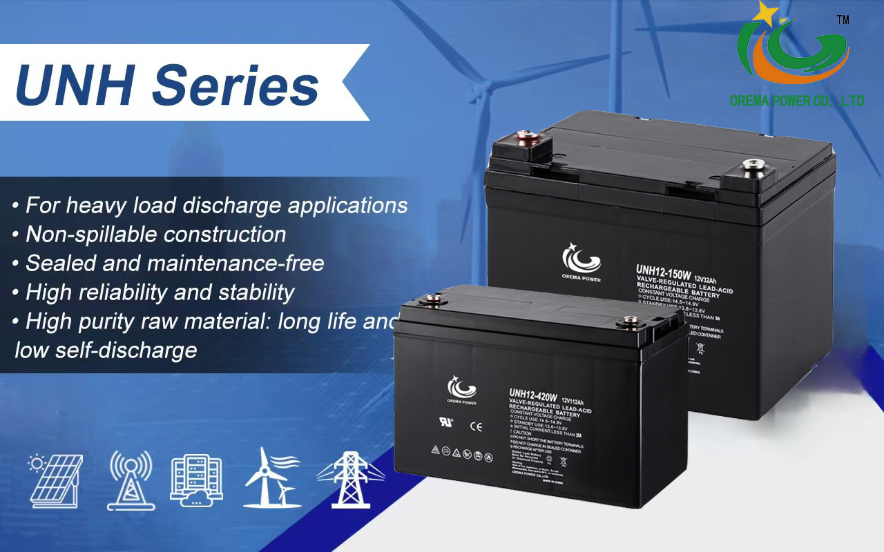
Our high rate discharge batteries, a core part of the OREMA UNH series, are designed for heavy-load discharge applications, promising a design life of 5-12 years in floating service. These batteries excel in delivering stable performance during high current discharges, thanks to robust grids and specially formulated active materials.
Advanced AGM Technology:
At the heart of our innovation lies the advanced Absorbent Glass Mat (AGM) technology. This cutting-edge approach guarantees consistent backup power, vital for UPS systems and other critical applications. The UNH series showcases exceptional high-power discharge performance, offering abundant power in short periods, making them ideal for applications needing quick and reliable backup power sources.
Reliability in Every Cell:
Renowned for their high reliability, our batteries withstand the rigors of continuous use, providing uninterrupted power when it matters most. This resilience makes them suitable for critical power applications where any downtime or power interruption could have severe consequences.
Durability and Longevity:
Beyond reliable performance, these batteries boast impressive durability. Designed for extended life, they can endure repeated charging and discharging cycles without capacity loss. This ensures they consistently provide backup power over an extended period, offering peace of mind to our users.
Features and Benefits of OREMA 12V High Rate Batteries:
High rate discharge construction for demanding applications.
Excellent deep discharge recoverability.
High energy density design, ideal for high current and high power discharge in UPS systems.
Slow self-discharge rate (<3% per month), ensuring constant power in standby or as part of a UPS system.
Heavy-duty, threaded copper alloy terminals for easy assembly, reduced maintenance, and enhanced safety.
High tin grid alloy minimizes gassing and delays corrosion, extending battery life with maintenance-free convenience.
Diverse Applications of OREMA High Rate Battery Pack:
Our high rate batteries are versatile, catering to a wide range of applications:
Standby Use: UPS power supplies, emergency lighting, precision instrument backup, fire alarms, security systems, office automation, and more.
Solar Cell Power Generation: Street lighting, portable power supply, water pumping stations, rural power systems.
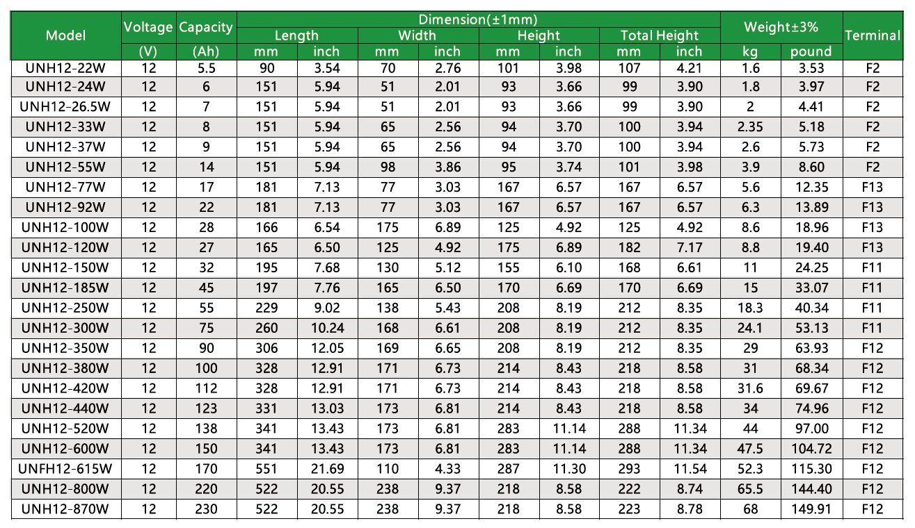
Specifications of OREMA UNH series high rate discharge batteries:
