In the 22nd issue of the Journal of Electrotechnical Engineering in 2017, researchers from the State Key Laboratory of Power Transmission and Distribution Equipment and System Security and New Technology at Chongqing University, including Ouyang Jinxin, Tang Ting, Zheng Di, Ren Wenjun, Xiong Xiaofu, and Zhong Jiayong, highlighted that the widespread integration of Doubly Fed Induction Generator (DFIG) wind turbines has significantly altered fault characteristics in power systems. This change poses a major challenge to the implementation of traditional relay protection schemes. Despite existing research on DFIGs, few studies have considered the impact of Low Voltage Ride-Through (LVRT) strategies on fault behavior. This paper investigates how the short-circuit current of DFIGs changes under LVRT control, particularly focusing on the influence of reactive power output on terminal voltage and fault characteristics. By constructing a vector model of DFIG under LVRT control, this study derives expressions for short-circuit currents before and after LVRT activation. It analyzes how the startup delay of LVRT affects the transient response of the system. A fault equivalent model is developed to represent the behavior of DFIGs both before and after LVRT is initiated, and a new method for calculating short-circuit currents in grid-connected DFIG systems is proposed. Variable-speed constant-frequency wind turbines based on DFIG are widely used in modern wind power generation. These systems rely on power electronic converters for excitation control and grid connection. During grid faults, wind turbines may disconnect, leading to power shortages [1]. As wind energy grows globally, grid codes now require wind turbines to have LVRT capability, enabling them to stay connected during faults and inject reactive power to support grid recovery [2, 3]. Unlike synchronous generators, variable-speed wind turbines exhibit different transient behaviors during grid faults [4]. When a fault occurs, large overcurrents can appear in the DFIG rotor, prompting the use of Crowbar circuits to protect the Rotor Side Converter (RSC) by providing an alternative path for the current [5]. While Crowbar protection allows continuous operation without disconnection, it transforms the DFIG into a conventional induction generator with high rotor resistance, limiting its ability to provide reactive power and meet modern LVRT requirements [6]. To address this, keeping the RSC connected during faults and adjusting stator reactive power within converter limits becomes a more effective approach for achieving LVRT [5, 7]. During such events, many wind turbines remain connected to the grid, injecting short-circuit current and reactive power, which alters fault characteristics [8, 9]. Understanding these effects is crucial for accurate fault analysis. Previous studies have focused on short-circuit current calculations under Crowbar action or normal operation modes, but few have considered the dynamic behavior under LVRT control. Reference [14] examined the impact of LVRT on fault processes, but neglected the transition phase. Moreover, many studies assume a constant terminal voltage post-fault, ignoring the effect of reactive power on voltage fluctuations. This paper investigates the characteristics and calculation methods of DFIG short-circuit current under symmetrical grid faults. It explores how LVRT control modifies the stator’s short-circuit current through adjustments in rotor excitation and terminal voltage. Based on the DFIG vector model under LVRT, the paper derives the short-circuit current expression and analyzes the impact of LVRT on the transient process. The study couples the fixed-rotor response with RSC-based LVRT control via terminal voltage, dividing the fault process into two stages—before and after LVRT activation. Corresponding fault equivalent models are established, and a new calculation method for DFIG short-circuit current is proposed. In conclusion, existing fault analyses of DFIG-based wind power systems often overlook the influence of reactive power output under new LVRT standards. This paper addresses this gap by analyzing the impact of LVRT control and its startup delay on the DFIG short-circuit process and output characteristics. It proposes a fault equivalent model for DFIG before and after LVRT activation and presents a calculation method that accounts for LVRT effects. The main findings include: 1) Under the new LVRT control, the DFIG's reactive power supports the grid voltage during faults, altering the terminal voltage and influencing the rotor winding's transient behavior through armature reaction and RSC control. This leads to changes in the short-circuit current. 2) The delayed activation of LVRT due to terminal voltage changes results in two distinct phases of voltage and current variation during the fault. The speed of LVRT activation directly affects the magnitude and dynamics of the short-circuit current. 3) Traditional short-circuit current analysis that ignores reactive power and LVRT startup delays fails to accurately capture the fault characteristics of DFIGs under modern LVRT standards. The proposed method provides a more precise representation of short-circuit current behavior, meeting the needs of power system fault analysis. UFO High Bay Lights Led Driver
UFO High Bay Lights Led Driver
Constant current LED driver, UL dimmable transformer, With global manufacturing standards and various certifications including CE, UL and FCC, our lighting products are sold in domestic market and are exported to various international markets including US, UK, France, Germany, Australia, Africa, Korea etc. We offer a wide range of LED lighting solutions which includes LED Linear Lighting or System, , LED Lams, LED High bay lights etc. Maximize beauty of your workplace with our beautiful Warehouse Lighting, warehouse lights driver, Workshop Lighting, Supermarket Lighting and Factory lighting solutions.
Application: Specifically for high bay light,High Power Led Driver above 100W,normal for outdoor for waterproof, AC100-277V, 0-10V/PWM/RX dimming,short circuit protection,class 2 satety output design, passed the UL/FCC/TUV/RCM/CB/CE Certified. Europe and North America market.
Parameter:
Input voltage: 100-277vac
Power:108-240W
IP degree: IP65
FAQ:
Industrial High Bay Driver,Heat Resistant Ufo Led Driver,200W Led Driver ShenZhen Fahold Electronic Limited , https://www.leddriversupply.com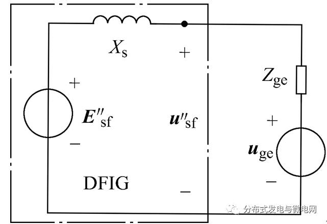
output voltage: 25-143vdc
current: 100mA-8000mA.
Power factor: >0.9
Dimming:0-10V / PWM / RX / DALI.
>=50000hours, 5 years warranty.
certificate: UL CE FCC TUV SAA ect.


Question 1:Are you a factory or a trading company?
Answer: We are a factory.
Question 2: Payment term?
Answer: 30% TT deposit + 70% TT before shipment,50% TT deposit + 50% LC balance, Flexible payment
can be negotiated.
Question 3: What's the main business of Fahold?
Answer: Fahold focused on LED controllers and dimmers from 2010. We have 28 engineers who dedicated themselves to researching and developing LED controlling and dimming system.
Question 4: What Fahold will do if we have problems after receiving your products?
Answer: Our products have been strictly inspected before shipping. Once you receive the products you are not satisfied, please feel free to contact us in time, we will do our best to solve any of your problems with our good after-sale service.