XTR105 circuit diagram, schematic The XTR105 is a 4-20mA current transducer with sensor excitation and sensor signal linearization. It adds linearization and reference voltage circuitry to the XTR101. The basic performance and electrical parameters are: two-wire or three-wire RTD-I, low temperature drift (0.4tLV gate C), low noise (30nAp-p), high CMRR (86dBt minimum), and working power is 7.5-36V. Its internal circuit function diagram is as follows: XTR105 Chinese data, English data manual Click here to jump to the page to download: XTR105 Chinese information Click here to go to the page to download: XTR105 English Data Sheet XTR105 application circuit diagram The XTR105 is a single-core integrated 4-20mA current source chip. The chip itself provides two high-precision current excitation sources that can be used for mirrored power supplies of platinum resistors or current sources for bridge resistors. Used to test temperature or pressure. The circuit itself has a gain-adjustable function that eliminates external op amps for cost savings. The XTR105 application circuit is shown below: The performance characteristics of the XTR105 are as follows: 1. Has a very low adjustment error; 2. With two high precision current mirror sources, 800uA each. 3. With good linearization, this can satisfy most engineering applications. 4. High voltage rejection ratio, high common mode rejection ratio, and a wide voltage operating range, which is convenient for power supply designers. 5. The lower offset (under temperature characteristics) is only 0.4 uv per 1 degree change, which is very good for the op amp indicator. Many single op amps do not have this indicator. The current noise is also very low, only 30na, this is the peak, and the average is lower than this level. As can be seen from the figure below, the characteristics analyzed above: Magnetic Buzzer Self-drive Type
The magnetic buzzers (Self-drive Type) offer optimal
sound and performance for all types of audible alert and identification. Our
magnetic Buzzer solutions are offered with various mounting options. We also
provide you with a washable version for your preferred soldering method. Our magnetic buzzers, also known
as indicators, are designed with an internal drive circuit for easy application
integration. During operation, current is driven through a voice coil to
produce a magnetic field. When a voltage is applied, the coil generates a
magnetic field and then allows the diaphragm to vibrate and produce sound. This
buzzer type has a low operating voltage ranging from 1.5 – 12V+. Our magnetic
buzzers are desirable for applications requiring a lower sound pressure level
(SPL) and frequency.
Passive Buzzer,Dc Magnetic Buzzer,Electro Magnetic Buzzer,Magnetic Buzzer Self Drive Type Jiangsu Huawha Electronices Co.,Ltd , https://www.hnbuzzer.com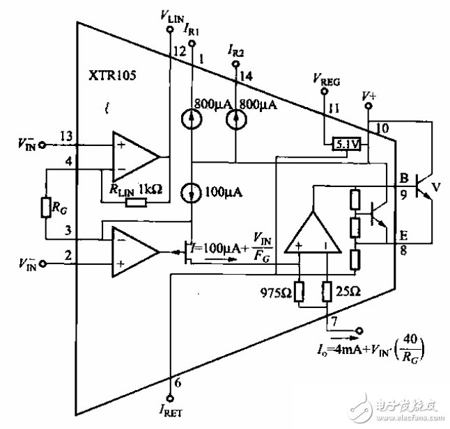
XTR105 circuit schematic 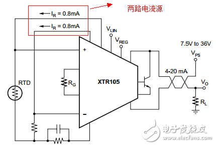
XTR105 application circuit diagram 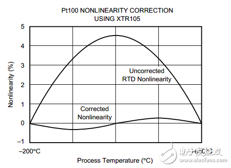
XTR105 characteristic curve