Introduction Audio receiving equipment is an indispensable tool in daily life, learning, and work. However, due to some reasons, such as switching channels, playing advertisements, etc., the volume of the signal will be different when the signal is output, which seriously affects the situation. User's listening experience. The main reason for this large difference in volume is that the amplitude of the audio signal input is inconsistent. The solution is to perform gain control. This article refers to the address: http:// Led Photo Clip Remote String Lights, 100 LEDs Fairy Twinkle String Lights, Wedding Party Home Decor Lights for Hanging Photos, Cards and Artwork (44 Feet, Warm White) DECORATE ANYWHERE - Portable string lights with infinite possibilities. It can be used outdoors, just be sure to protect the USB cord/port from rain/snow/etc. if you choose to put the lights outdoors. This is a SIMPLE AND ELEGANT way to take your room to the next level. This is the PERFECT GIFT for your friends and family that. Give the most creative and functional gift this year! PACKAGE (whats in the box) - 44 feet light string including 100 LED lights -USB Cable -100 transparent clips -12 wall hooks Christmas String Lights,String Lights With Clips,Led Photo Clip String Lights,Led Clip String Light Dongguan Xingyong Indusrtial Co,Ltd , https://www.xingyongled.com
The earliest gain control is analog circuit detection control, but the analog circuit design is relatively cumbersome, and it is difficult to achieve a wide range of gain control. Therefore, with the development of digital signal processing devices (DSP), the use of DSP for gain control has become mainstream. At first, the general method of digital device processing is that the large signal reduces the gain and the small signal does not. There are also methods for amplifying small signals, but since the gain adjustment is too large without signal input, the background noise is also increased, so the gain adjustment range is not large and the ideal control effect cannot be achieved. In addition, the input signal is basically detected, that is, feedforward control, the output signal is not detected, so if the gain is large when inputting, the output will be limited, affecting the listening effect. And the cost of the DSP solution is relatively high. This scheme uses a low-cost single-chip microcomputer as the processing core, and completes the gain automatic control through a simple gain control algorithm.
1 system hardware design As shown in Figure 1, the whole system is designed with the audio signal acquisition and processing as the core. The audio signal input and output terminals on both sides of the audio control chip PGA2311 are sent to the A/D port of the MSP430F149 for sampling after being level-shifted by the amplifier TL084 (the signal input/output terminals are all detected to solve the problem that there is no signal at the input end). Whether the gain is adjusted or not, and avoiding excessive gain causes the output limit to occur). The sampled data is processed by a software algorithm to obtain a gain value, which is configured by the level converter 74HC245 to the PGA2311. The buttons and the digital tube complete the setting and display of the output level threshold range. 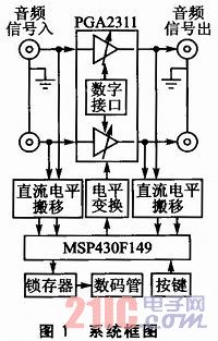
1.1 The main control circuit main control chip MSP430F149 is a 16-bit, 48 8-bit parallel I/O port, with a reduced instruction set, ultra-low power consumption (minimum 0.1μA in power-saving mode), its The addressing space is 64 KB and the RAM is 2 KB, which brings great convenience to system development. It has a 12-bit A/D converter ADC12, sample and hold, and analog multiplexer. The ADC12 features high speed, versatile features that enable A/D conversion of eight external analog sources and four internal reference sources, including internal temperature sensor sources. The ADC12 also offers a variety of sample trigger modes, conversion clock cycles, and conversion mode options.
The PGA2311 is a two-channel, programmable gain amplifier that interacts with the MSP430F149 via the SPI bus with a gain range of +31.5 to -95.5 dB.
The MSP430F149 in Figure 1 is powered by 3.3 V, while the PGA231l is a ±5 V-powered CMOS device. Therefore, care should be taken when matching the I/O logic levels to achieve level matching with the level shifter 74HC245 when driving the PGA2311.
1.2 Level shifting circuit Because the volume of the general audio output device is different and is AC-coupled, the A/D sampling voltage range of the MSP430F149 is 0-2.5 V, in order to avoid matching the sampled signal with A/D. Clipping distortion requires scaling (or reducing) the input signal and moving the center voltage to around 1.25 V. as shown in picture 2. 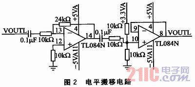
2 Software Design The software design includes key display, peripheral control, and audio signal processing. The focus is on the AGC algorithm for audio signal processing. The button display responds to the user setting the output volume level and displays it. The peripheral control is mainly to configure the PGA2311.
2.1 AGC algorithm The core of the AGC algorithm is to judge whether the dynamic range of the signal exceeds the set size by the envelope information of the signal. Here, it is necessary to quickly track the change of the envelope and perform gain control in time.
In the conventional AGC algorithm, the multiplication and division operation has a large occupation of CPU resources. The AGC algorithm proposed here is relatively simple and practical, and its flow is shown in Figure 3. The specific implementation process: from the A / D port of the microcontroller, the level of the audio input / output signal is stored in an array. The array stores the data to meet the threshold comparison requirements and enters the peak comparison process. According to the stored input signal data, the algorithm of bubble sorting is used to find the maximum amplitude, and it is judged whether there is a signal at the input end. If it is determined that there is no audio signal input, the gain is not adjusted to prevent the gain from being increased due to the output signal being too small, the noise is too large, or once the sound is present, the short-time output sound is too large due to the excessive gain. If there is a signal at the input, the output is detected. The bubble sorting program is also called to find the maximum amplitude. If the output signal exceeds the set threshold, the gain is reduced, otherwise the gain is increased. When the gain is reduced, the step is larger, and the step is smaller when the gain is increased, so that the volume outputted during the gain adjustment makes the user feel uncomfortable.
3 Experimental demonstration To demonstrate the correctness of the design, the experimental demonstration. Set the output level range, input the abrupt audio signal from the computer, and observe the output through the oscilloscope, as shown in Figure 4. 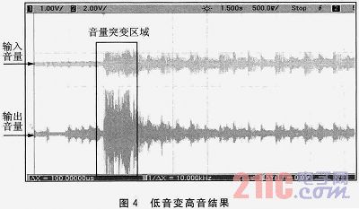
From the sudden change in volume indicated by the box in Figure 4, it can be seen that after the input volume suddenly increases, the gain is turned down within 500 ms, and the volume output is kept output within the set range. Experiments such as treble mutant bass are not illustrated here because the adjustment period is long.
The conclusion experiment results show that the design gain control is timely and accurate, and the output signal level is stable output in the set range, and the power consumption is low, the implementation is simple, and the portability is strong, which can meet the current user requirements for the volume output of the audio receiving device. .