In many products, low or medium speed fans are sufficient to dissipate heat while allowing the highest speed mode to be maintained to cope with the worst case scenario. The circuit described in this article uses linear voltage control and reduces noise by reducing the fan speed by operating the fan at a DC voltage below the manufacturer's full rated voltage.
SMBus Temperature Sensor IC
Commercially available SMBus temperature sensor ICs include sensors that measure the ambient temperature around the IC and devices that support one or more external sensors (ie, some inexpensive diodes connected to the diode).
The SMBu communication interface provides an easy connection to the system microcontroller, while the temperature sensor's measurement parameters can be configured via a writable register.
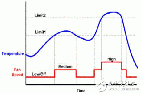
Figure 1: The relationship between the temperature set by the control circuit and the fan speed in this paper.
Many SMBus temperature sensors have one or two outputs that work when the temperature exceeds a certain limit (programmed into the IC register) (typically low). Design engineers are expected to achieve typical sensor accuracy of 1 to 3 ° C and fine to 1 / 8 ° C resolution.
The universal drive voltage for most DC brushless fans is +5V and +12Vdc. Fans running at full speed produce annoying noise, so it is important to keep the speed of the fan as low as possible. Operating the DC fan at a reduced voltage and as the fan ages, the fan starting voltage becomes a limiting factor as bearing wear can cause the required starting voltage to increase.
The actual operating voltage range of the fan varies greatly. A manufacturer's rated +5V fan may start with 2Vdc, while another fan of the same size and size may require 4Vdc to start. When the operating voltage of the selected fan is lower than the manufacturer's rating, it is important to extract the fan characteristics and add some margin, considering the wear and the difference between the fans.
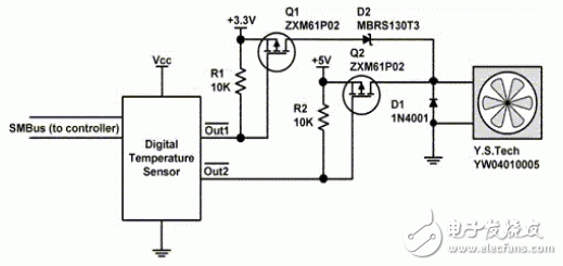
Figure 2: Two triodes drive a 5V fan drive.
intelligent control
1. Two triodes enable 5V fan drive:
The circuit shown in Figure 2 is useful for fan products powered by +3.3V and +5V. When the temperature is below the two limit settings, the open-drain outputs Out1 and Out2 are set high, causing R1 and R2 to pull the gates of P-channel FETs Q1 and Q2 high, turning them off. When the temperature exceeds the limit value 1 in Figure 1, Out1 goes low, Q1 is turned on and a voltage of about 3V is applied to the fan through the Schottky diode D1. When Out2 goes low, Q2 turns on and applies a voltage of 5V to the fan. D2 ensures that the 5V supply will not react to the 3.3V supply through Q1.
This circuit is very efficient because the base of the triode does not consume current. Its function is to switch and connect the fan directly to the power rail. Selecting Ron's 0.75Ω@ Vgs=3V P-channel FET keeps the voltage drop and power consumption low. Low power consumption allows the fan to use a small form factor SOT-23 device to achieve a current rating of 400mA@5V.
2. Single triode for 5V fan drive
.
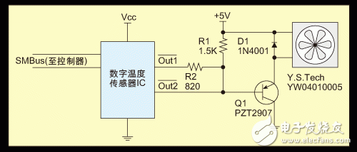
Figure 3: Single Transistor for 5V Fan Drive
The circuit shown in Figure 3 uses a PNP transistor to control the three speeds of the fan: stop, medium, and high speed. Both Out1 and Out2 go high when the temperature is below the two limit settings. There is no current flowing through the base of Q1, so it turns off and the fan voltage is 0V.
When the temperature exceeds the limit value 1, the Out1 drive goes low and the resistor divider R1/R2 sets the voltage of the base of Q1 to 1.8V. Since the base voltage is Vbe, the emitter voltage will be 0.7V higher than Vbe, resulting in a fan voltage of 2.5V (50% of full scale voltage).
When Out2 goes low, it pulls the base of Q1 low to ground, and the base current is limited by the maximum absorption capacity of the IC output. The typical value is @Vol=0.4V“â€6-8mA@Vol=0.4V. The base current is limited and the gain of Q1 should be greater than 100 to ensure minimum voltage drop and strong triode drive capability. The voltage drop between the output device and Q1 limits the maximum fan voltage to 4.1V (82% of full scale voltage).
3. Single triode for 12V fan drive
The circuit shown in Figure 4 is slightly different from a single triode circuit that can drive the fan to operate at low, medium, and high speeds. This arrangement allows the 12V fan to be controlled by an IC that outputs a maximum voltage of 5V.
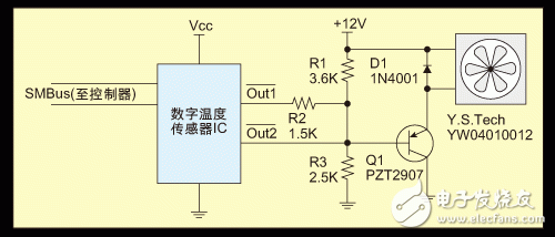
Figure 4: A single triode implements a 12V fan drive.
When both outputs of the IC are high, the low speed is set by resistors R1 and R3. The R1/R3 voltage divider sets the Q1 base voltage to 5.0V, which provides the fan with a voltage of approximately 6.3V (52% of full scale voltage). When Out1 goes low, a medium speed can be achieved, and the base voltage is set to 2.5V and the fan voltage is 8.8V (73% of full-scale voltage) by sinking current through R2. When Out2 goes low, the high-speed voltage reaches 11.1V (92% of full-scale voltage).
Summary of this article
The SMBus temperature sensor controls the three speeds of the fan, and its system design flexibility is high and the cost is low. By operating at a lower two fan speeds for normal and above average power consumption, the fan speed can be set for silent operation. The maximum speed can be dedicated to operation under extreme temperature conditions, where cooling takes precedence over silent operation.
Porcelain Station Post Insulator according to IEC, ANSI and other standards are used in substations and related switching equipment. Station Post Ceramic Insulator are produced in single piece up to 2300 mm and can operate voltages up to 1100KV in stacked configuration. High Voltage Station Post Insulator are subjected to compression, cantilever and torsional loads during service. Station Post Insulator for high voltagr use semiconductor glazes, so you don't have to worry about salt deposits or corona discharges.
Product Description
1.Material: Porcelain
2.Improved contamination performance
3.Widely applied to the line of different voltage classes
4.With features of good insulation performance
5.Long lasting durability
|
MAIN DIMENSIONS AND STANDARD PARTICULARS
|
|
Type
|
C4-125
|
|
Creepage distance(mm)
|
430
|
|
Dry arcing distance(mm)
|
200
|
|
Cantilever strength(KN)
|
4
|
|
Tension Strength(KN)
|
38
|
|
Torsion strength(N.m)
|
800
|
|
Power frequency flashover wet voltage(KV)
|
50
|
|
Impulse withstand voltage(KV)
|
125
|
|
Net weight(KG)
|
9
|
|
MAIN DIMENSIONS AND STANDARD PARTICULARS
|
|
ANSI Class
|
TR-205
|
TR-208
|
TR-210
|
|
Creepage Distance/mm
|
394
|
610
|
940
|
|
Cantilever Strength/kn
|
8.9
|
8.9
|
8.9
|
|
Tensile Strength/kn
|
38
|
44.5
|
53
|
|
Torsional Strength/k.m
|
791
|
904
|
1130
|
|
Compression Strength/kn
|
44.5
|
44.5
|
66.7
|
|
Low Frequency Dry Flashover Voltage/kv
|
85
|
110
|
145
|
|
Low Frequency Wet Flashover Voltage/kv
|
55
|
75
|
100
|
|
Critical Impulse Flashover Voltage, Pos/kv
|
125
|
170
|
225
|
|
Critical Impulse Flashover Voltage, Neg/kv
|
200
|
250
|
290
|
|
Low Frequency Dry Withstand Voltage/kv
|
50
|
70
|
95
|
|
Low Frequency Wet Withstand Voltage/kv
|
45
|
60
|
80
|
|
Impulse Withstand Voltage/kv
|
110
|
150
|
200
|
|
Net Weight/kg
|
7
|
11
|
16
|
|
Applicable Standard
|
ANSI C29.9
|
ANSI C29.9
|
ANSI C29.9
|

 We warmly welcome friends both domestic and abroad to visit our company, if you have any questions, please contact with us directly.
Station Post Insulator
Station Post Insulator,Station Post Ceramic Insulator,High Voltage Station Post Insulator,Post Insulator For High Voltage
FUZHOU SINGREE IMP.& EXP.CO.,LTD. , https://www.cninsulators.com