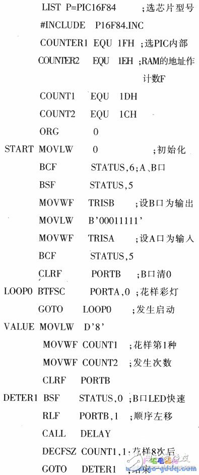
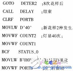
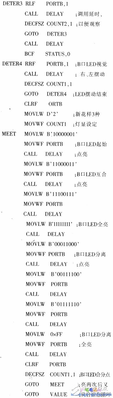
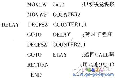
1. The RLF instruction is used to shift the contents of register f along with the carry bit (C) to the left in a loop. 2. The RRF instruction shifts the contents of register f along with the carry bit (C) to the right in a loop. Designing a pattern lantern controller using a PIC microcontroller can be straightforward by employing loop instructions and delay routines. This approach simplifies the overall software structure significantly. In this example, we use a simple program to demonstrate the functionality of the pattern lantern. The source code is named "PIC07.ASM," and it includes multiple routines for generating different LED patterns. The full source listing is provided below: Description: Adjustable Aluminum Laptop Stand, Nulaxy Adjustable Aluminum Laptop Stand, Amazon Aluminum Laptop Stand Shenzhen ChengRong Technology Co.,Ltd. , https://www.laptopstandsupplier.com
Format: RLF f, d. When d=1, the result is stored back in register f; when d=0, the result is placed in the W register. The function is illustrated below.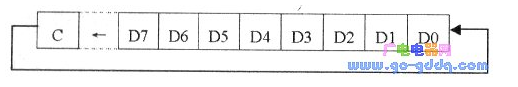
Format: RRF f. The value of d follows the same logic as in the RLF instruction, and the operation is shown in the figure below.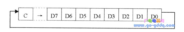

(1) There are over 80 different source programs available for the pattern lanterns. These programs use the B port of the PIC16F84A microcontroller to simulate LED outputs, producing five different visual patterns.
(2) If you plan to turn the pattern lantern into a commercial product, the B port can be used to drive solid-state relays (which will be discussed in the next article), allowing real-world display applications. In some cases, expanding the B port may be necessary to support more LEDs or additional functions.
(3) The pattern lantern operates at high speed, which is why the PIC16F84A is configured with a 4MHz clock frequency to ensure smooth and responsive performance.