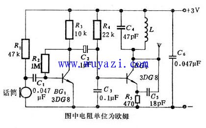
This compact device is about the size of a matchbox and features a simple electrical schematic. The inductor L is wound with 5 turns on a 3 mm drill bit using high-strength enameled wire (diameter between 0.5–0.7 mm) with spacing of approximately 5.5 mm. The resistor used is a 1/16 watt RTX type, while the capacitors are small CC1 ceramic types, except for the electrolytic capacitor. The transistor can be a 3DG8 or 3DG6 model, provided that its β value is above 100. A condenser microphone is used, and adjusting the resistance R1 allows control over the microphone's sensitivity—higher resistance increases sensitivity, with R1 typically ranging from 10–100 kΩ. The antenna can be a 10 cm long wire soldered to the BG2 collector. The power supply consists of two No. 5 dry batteries. After assembling all components, the circuit can be tuned. The normal collector voltage of BG1 should be around 1.4 volts, and the collector current of BG2 should be between 4–6 mA. During debugging, avoid placing your hands too close to the transmitter and use a non-inductive screwdriver. The center frequency of the carrier signal is mainly determined by C4 and the inductance L. Increasing the length of the inductor L will raise the carrier frequency. Keep the transmitter away from the FM radio during tuning to prevent interference from higher harmonics. When tuning the FM radio, you should normally receive a carrier signal between 80–108 MHz. If the receiver only detects the carrier without any audio, the issue may lie with the audio amplifier or the condenser microphone. Under normal operation, the condenser microphone should show a voltage between 0.7–1.5 volts. Once fully operational, the output power can reach 5–8 mW, allowing a transmission range of up to 100 meters. This simple and effective design is ideal for basic wireless microphone applications and is easy to build and adjust for optimal performance. Three Phase Voltmeter,Control Device,Digital Instrument,Voltage Meter,Multifunctional digital panel voltmeter zhejiangjinyidianqiyouxiangongsi , https://www.jooeei.com