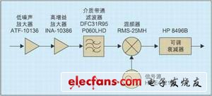
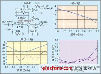
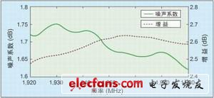
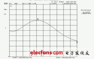
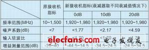
Noise figure is one of the key indicators of radio frequency circuits in wireless communication. It determines the sensitivity of the receiver and affects the signal-to-noise ratio of the analog communication system and the bit error rate of the digital communication system. The rapid development of wireless communication requires higher and higher noise performance of radio frequency circuits, and the frequency band used by wireless communication is also developing higher. This requires accurate measurement of the noise figure at high frequency bands. The highest measurement frequency of the older generation noise figure tester is lower. In order to measure the noise figure of the circuit at a high frequency band, an external mixing module is required to down-convert the signal in the frequency band to be measured to the frequency range of the receiver of the noise figure tester. The calibration and measurement block diagram of the measurement system is shown in Figure 1. The new measurement system receiver consists of a cascade of mixing modules and the original receiver. The measurement principle is to use the Y parameter method to obtain the noise temperature of the new receiver through calibration; after inserting the device under test (DUT), measure the noise temperature of the cascade of the DUT and the new receiver, and then use the cascade noise temperature calculation formula to obtain the DUT Noise temperature at high frequencies. Extend the measurement frequency range of HP 8970A from 10MHz to 1.5GHz to 1.92GHz to 1.98GHz, including the uplink frequency band of W-CDMA in the third-generation mobile communication (3G) standard. Mixer module structure amplifier schematic, measurement and simulation results (dashed lines indicate measurement results, solid lines indicate simulation results). The error of noise figure measurement is mainly determined by the structure and noise figure of the receiver of the measurement system, the uncertainty of the receiver noise figure, the uncertainty of the noise source, the matching of each port during calibration and measurement, and the gain of the DUT. For a measurement system externally connected with a mixing module, in order to improve the measurement accuracy, the mixing module needs to have a single sideband structure, a smaller noise figure, and a smaller input port standing wave ratio. In order for the new receiver to have a low noise figure, the mixing module must have a certain gain, and its gain determines the gain measurement range of the noise figure tester. In order to meet the measurement needs of different gain DUTs, the mixing module's Finally, an adjustable attenuator HP 8496B was added. The local oscillator is provided by the signal source HP E4421B with a fixed frequency of 2.5GHz. The mixer down-converts the radio frequency signal from 1.92GHz to 1.98GHz to 0.52GHz to 0.58GHz, and the corresponding image signal frequency is 3.02GHz to 3.08GHz. The circuit structure of the mixing module is shown in Figure 1. Mixing module design 1. Low noise amplifier design The uncertainty of noise figure measurement increases as the noise figure of the receiver of the measurement system increases. The noise figure of the receiver of the new measurement system is determined by the noise figure and gain of the mixing module and the noise figure of the original receiver. In order to reduce the noise figure of the new receiver and improve the measurement accuracy, the mixing module needs to have a low noise figure and a certain gain. The low-noise amplifier is composed of two stages. The first stage uses the field effect tube ATF-10136, which provides a noise figure of less than 0.9dB and an input standing wave ratio of less than 1.5 in the frequency band from 1.92GHz to 1.98GHz; the second stage uses a monolithic microwave The integrated circuit (MMIC) INA-10386 has a typical gain and noise figure of 23.6dB and 4.2dB in the frequency band. It can compensate the loss of the post-stage filter and mixer, so that the new receiver has a low noise figure. The input and output matching network has been designed inside the INA-10386, so the circuit form is simple, only the bias circuit and the input and output DC blocking capacitors need to be added, but it is worth noting that the ground pin must be as close as possible to the via, Otherwise, the amplifier will self-excited. In order to obtain a small input standing wave ratio and low noise figure, the design of the ATF-10136 low noise amplifier needs to take into account noise matching and input power matching. By adding a small section of microstrip line at the source of the FET as feedback, the best noise matching and the best power matching point are closer, and the stability of low frequency is improved; the source DC passes through the resistor to ground, and the gate DC directly to ground , Providing negative voltage for Vgs, using a single + 5V power supply; a 10Ohm resistor in series at the output end to improve the stability of the amplifier in the entire frequency band; matching inductors use Toko LL2012-FH series high-Q, multilayer ceramic chip inductance. Use the Agilent Advanced Design System (ADS) for design and simulation. The simulation and actual measurement results are shown in Figure 2. The simulation and measurement results are very close. This is due to the fact that the S-parameter model of the inductor is used in the simulation instead of the ideal model, and the parasitic effect of the lumped element and the abrupt characteristic of the microstrip line are considered. 2. Selection of mixer and image rejection filter The mixer uses the RMS-25MH passive mixer from Mini-Circuits, with a local oscillator frequency of 2.5GHz and a power of 14dBm. The mixer converts the RF signal at the input frequency of LOIF to the intermediate frequency. If no RF filter is added, the measured noise figure of the double-sideband is the result of measuring both the upper and lower sidebands. In order to perform single-sideband noise figure measurement, a filter needs to be added to the RF input of the mixer to suppress the image signal. The image suppression filter uses Murata's DFC31R95P060LHD dielectric band-pass filter with a center frequency of 1,950MHz and a bandwidth of 60MHz. The passband insertion loss is less than 3.5dB, and the standing wave ratio is better than 1.5. New measurement system indicators When the attenuation of the adjustable attenuator is 0dB, using the 1.4 measurement mode of the HP 8970A, the noise figure and gain of the mixing module are shown in Figure 3. The typical values ​​of the noise figure and gain are 1.7dB and 25.5dB. Since the first stage of the mixing module has a very low noise figure, and the first two stages have higher gains, the noise figure of the entire mixing module is very low. The measurement result of the input standing wave ratio of the mixing module is shown in Figure 4. The specifications of the receiver of the new noise figure tester and the original receiver are shown in Table 1. Conclusion of this article The author successfully designed a low-noise mixing module that extends the measurement frequency range of the noise figure tester HP 8970A to 1.92GHz to 1.98GHz. The low-noise amplifier in the mixing module has a low noise figure, a small input standing wave ratio and a high gain in a wide frequency band of 1.6GHz to 2.2GHz, and only need to select different image suppression filters to obtain different frequency bands The mixing module with internal noise figure has good scalability. The gain of the mixing module is adjustable, which can meet the measurement requirements of different gain DUTs. Compared with the original receiver, the new receiver has a comparable input standing wave ratio and a smaller noise figure.
Available in 10W, 30W, 50W, 100W, 150W, 200W and 300W
versions, range of IP65 floodlights are ideal for residential applications and
commercial security requirementsns,. LED Flood Light through the built-in
micro-chip control, the existing two types of products, one type of power chip
combination, and the other with a single high-power chip, the former
performance is more stable, single high-power product structure is large,
suitable for small Range of light exposure, which can achieve a high power, can
be a large area of long distance cast light.
LED Flood Light With Driver,LED Flood Light Fixture,LED Flood Lamp,LED Flood Lighting Shenzhen Ri Yue Guang Hua Technology Co., Ltd. , https://www.ledlightinside.com