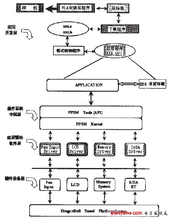
The function and structure of home PDA based on home network are introduced, and the specific implementation methods of key technologies are discussed. As a special case of the development process of embedded devices, the role of the embedded operating system in the embedded device and its relationship with other parts are pointed out. 1 Introduction The digital home information system builds a networked home information system consisting of a low-speed automation network and high-speed audio and video networks inside the home. The "home PDA" is an integral part of the digital home information system. It is completed by real-time communication with the home server. Control and management of home equipment. In order to achieve this goal, it is necessary to complete the establishment of the model of the device (including: display model, control model), two-way communication, graphics, text display, touch screen control and management, 16x16 dot matrix Chinese character library, the drive of the underlying device, etc. The specific home equipment to be controlled includes: TV, air conditioner, door, window, lighting. Among them, the parameters to be controlled by the TV include: mode, channel, volume, switch status, etc .; the parameters to be controlled and displayed by the air conditioner include: switch status, working mode, temperature, wind speed, etc .; the door, window, and lighting control the switch status. The home PDA has a liquid crystal display interface and a low-speed network interface, which can be used to monitor the working status of various home facilities, and can realize the unified control of all devices on the network (including home equipment and audio and video equipment), it can monitor the equipment Network access, network exit and working conditions, and can automatically model various terminal devices. 2 The software system framework structure and the relationship between all levels The software system mainly includes: the underlying device driver module, PPSM kernel, PPSM Tools (API), application layer client application development, programming program design and other parts. The hierarchical relationship is shown in Figure 1: Figure 1 Framework structure of software system and its hierarchical relationship 3 The connection between the software modules and the relationship with the overall system In this system, the software is mainly composed of: bottom layer driver software, PPSM operating system as the middle layer, upper layer application software and so on. Among them: the underlying driver software serves the operating system, and the operating system serves the development of the upper application software. 3.1 Low-level driver software The underlying driver software mainly includes the following modules: touch screen and pen input module, LCD driver module, FLASH programming module, initialization setting module of the underlying device, infrared communication module and other components. The main purpose of the touch screen and pen input module is to provide the underlying support of the touch screen and pen input for the PPSM operating system according to the actual situation of the target board, thereby facilitating the user's programming work. The ADC7843A / D converter is used on the target board. This software module The main function is to control its work through MC68EZ328. The LCD driver module screen is composed of a touch screen and an LCD display. The LTD79Z202LlGK LCD display is used in the system. The tasks to be completed include: controlling the frame refresh rate and controlling the LCD start address Registers, control LCD width and height registers, configure LCD interface registers, configure LCD polarity registers, configure LCD clock control registers, configure LCD brightness control registers, etc. In the infrared communication module, due to the limitation of CPU peripherals, infrared communication and serial port share a UART port. In order to achieve the common use of the two, the chip MAX3l30 is used to complete this function. In this way, it is necessary to control the working mode of MAX3l30 through the software system, so that it can select the appropriate working mode at the appropriate time, and the communication rate used is 2,400bit / S. The UART port has a transmission buffer of 8BYTE and a reception buffer of l2BYTE , Communication is completed by regular query, in order to ensure no data overflow, the query rate is 25mS. The initialization setting module of the underlying device is mainly responsible for the control of the working state of the system, the setting of the chip selection logic, the selection of the base address, the control of the DRAM controller address and refresh rate, the setting of the PLL register, the PWM control register and its duty cycle. Setting, PA port, PB port, PC port, PD port, PE port, PF port, PG port function, direction, initial value, pull-up resistor setting control, etc., interrupt the control system setting and other functions. The FLASH programming module is a module with relatively independent functions. It can be used as both a part of the underlying driver software and a part of the application software. Its main function is to solidify the programs and data downloaded into the dynamic memory of the target board into the FLASH of the target board.
With the continuous upgrading of terminal consumption in smart city, LED lamp pole screen, as an indispensable information carrier in smart street lamp system, is welcomed by many media companies and government agencies.
LED light pole screen is mainly installed on the street light pole on both sides of the highway and the street. Because the light pole display screen has the characteristics of synchronous reception and synchronous playback, no matter how far the car goes, it is always accompanied by the HD light pole display screen. The lamp post display screen not only has unique advantages in road guidance, road condition broadcast, information release, advertisement promotion, etc., but also plays a considerable role in alleviating the fatigue of automobile drivers on the highway.
LED intelligent light pole screen can quickly get the favor of consumers, which comes from the following natural advantages:
1. It has multiple control modes of WiFi / 3G / 4G / network cable, and the Internet can update the display content of light pole screen remotely, which is simple, fast and convenient
2. The high-definition intelligent lamp pole screen adopts the best three in one technology of waterproof and UV resistant SMD in the industry.
3. The intelligent LED light pole screen presents a full outdoor high-definition and high-definition picture. It uses RGB deep gray processing to support the point by point annotation function to maintain the consistency of advertising content and color brightness. Let the color of the advertisement more gorgeous, the picture quality more high-definition exquisite.
4. The lamp pole screen body is equipped with fixed stiffener plate, which can be tensile, shockproof, self cooling, and extend the service life;
5. The high-definition intelligent lamp pole screen has the protection grade of IP65 and is not afraid of any bad weather.
Lamp Post Pole LED Screen for Advertising,Advertising Lamp Standard LED Display,Street light pole led display,Double-edged led Lamp Post Shenzhen Vision Display Technology Co,.LTD , https://www.ledvdi.com