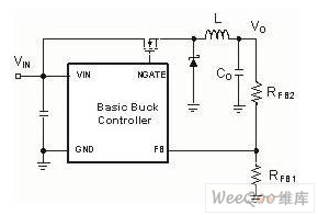
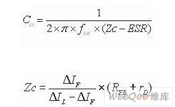
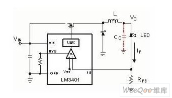
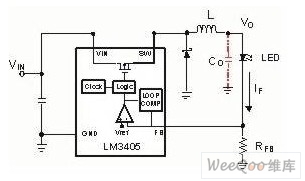
In the first part of the article, we studied the basic LED light source and driving method. Some simple driving methods are introduced, such as voltage source/current limiting resistors and linear regulated power supply. However, the power requirements and complexity of LED light sources are increasing, making these simple driving methods no longer satisfactory. This requires a more advanced switch mode LED driver. So what kind of switching method do we choose? In the second part, we will discuss why the switching mode LED driver uses the constant current step-down circuit to perform best, or in other words, why use the buck mode? With the widespread use of LEDs, the simple structure of linear power supplies in many places is no longer sufficient. In general, when the forward current required by the LED is set by means of a resistor, this simple driving method can continuously supply energy to the load from the power source. Since the current of the LED is the same as that of the resistor, the power dissipation generated by the resistor increases as the input voltage increases. For example, an LED driven by a linear power supply, with an efficiency of 70%, supplies 1A current to a typical white InGaN LED (VF = 3.5V) with a 5V linear supply. Under the same working conditions, when the input voltage rises to 12V, its efficiency will drop to 30%. It can't be applied in such an inefficient situation. Switching power supply The switching power supply improves the problem of a large change in efficiency due to input variations. This method is to control the duty cycle to meet the voltage or current required for the output. Since the switching power supply generates pulsed voltages and currents, it is necessary to shape these pulse waveforms with some energy storage devices (inductors or capacitors). In contrast to linear power supplies, switching power supplies can be implemented with different settings to achieve current or voltage drop, rise, or simultaneous lift. Switching power supplies can also achieve high efficiency over a wide range of input or output. In the previous example, after replacing the linear power supply with a step-down switching power supply, the efficiency of the circuit was changed from 95% to 98% when the input voltage was changed from 5V to 12V. The switching power supply has been greatly improved in efficiency and structural flexibility, but the noise is increased due to the periodic switching, and the reliability of the circuit is lowered and the cost is increased due to the complexity of the structure. The constant current type LED circuit can be simply considered to be a constant current source. The choice of topology should be based on the minimum of external components and the best performance, which can improve circuit stability and reduce costs. In view of the dynamic dimming characteristics of LEDs, it is necessary to consider this feature in the design. Fortunately, the basic buck switching circuit performs very well when implementing these features, so the LED driver generally selects a step-down switching power supply. Constant current output stage The most common switch regulator is the voltage regulator. Figure 1a shows a basic constant voltage buck regulator. The buck controller keeps the output voltage constant by controlling the change in duty cycle or frequency with varying input voltages. The voltage required for the output is calculated by the following formula (Eq. 1) Figure 1a: Basic Step-Down Voltage Regulator Inductor L is used to set the peak-to-peak value of ΔIpp of the inductor current ripple. Capacitance Co is used to set the output voltage ripple and the load transient response of the output voltage. In this buck inverter, the average current of the inductor is equal to the load current, so we can control the load current by controlling the peak-to-peak value of the inductor current ripple. This allows the voltage source control mode to be converted to a current source control mode. Figure 1b shows a basic current mode buck regulator. Similar to the constant voltage type, the constant current type buck regulator keeps the output current IF constant by controlling the duty cycle or frequency change in the case of a change in input voltage. The current required for the output is calculated by the following formula (Eq. 2): Figure 1b: Basic current type buck regulator After we set the LED current IF, we must accurately detect the current on the inductor. In theory, there are many ways to detect the inductor current, such as using the MOSFET's on-resistance Rdson or using the inductor's DC resistance. However, in fact, these detection methods cannot meet the requirements of LED current setting in accuracy (the accuracy of high-brightness LEDs is 5%-15%). If the IF is directly detected by the resistor RFB, the accuracy can be satisfied, but additional power consumption will be generated in the resistor. By lowering the feedback voltage VFB, the resistance of the sense resistor can be reduced in the case of the same sense current IF (Fig. 2), thus minimizing power consumption. Most of the latest LED drivers offer a reference voltage (feedback voltage) between 50 and 200 millivolts. The constant current buck regulator is unique in that the output does not require a capacitor. Because of the continuous output current and the absence of load transients, the output capacitor in this regulator is limited to current filters. When we set the constant current type buck regulator without capacitor, the output impedance will increase greatly. For the boost type, the output voltage will increase greatly in order to satisfy the constant output current due to the increase of the output impedance. . As a result, both the speed of dimming and the range of dimming have been significantly improved. The range of dimming from the perspective of backlighting and machine vision is a very valuable feature in the application process. On the other hand, due to insufficient output capacitance, the AC current ripple circuit requires a relatively large inductor to meet the LED ripple requirements (forward current ΔIF = ±5 to 20%). Large inductors increase the area and cost of LED drive during the same current ripple. Therefore, in a constant current step-down circuit, the use of output capacitors is traded between cost, area, and speed and range of dimming. For example, to drive a 1A white LED (VF ≈ 3.5V) with ripple current, ΔIF needs to meet ± 5%, input voltage 12V, frequency is 500kHz, and only 50mH is allowed when the inductor current amplitude is 1.1A. Inductance. However, if the inductor's ripple current is allowed to increase by ±30%, the inductance will be less than 10mH. If the 10mH and 50mH inductors use the same material and the same rated current, 10mH is about half of 50mH in terms of cost and volume. In order to achieve the required ΔIF (±5 %) with a 10mH inductor, the output capacitor needs to be calculated based on the dynamic resistance rD of the LED and the sense resistor RFB and the impedance of the capacitor at this switching frequency. The following expression (Eq. 3) can be used. Loop control structure The buck-based structure can be well matched to many loop control structures without regard to stability constraints, such as the right half plane zero point problem. In addition to being compatible with other dimming methods, this buck configuration makes PWM dimming easy. LED drivers based on this structure allow system designers to offer more options. Hysteresis control is ideal for applications where switching frequency changes are relatively fast and input ranges are small, such as white paper bulbs and traffic lights. Since the hysteresis control does not consider the stability limit, there is no need to consider loop compensation. Not as limited by bandwidth as loop control. Driving hysteresis LED drivers with hysteretic control (Fig. 2a) makes design simpler and reduces the number of components and costs. This structure also makes the PWM dimming range better than other structures. LED drivers with hysteretic control are ideal for applications where the dimming range is very large and the dimming frequency is high and the switching frequency varies greatly. Figure 2a: Basic hysteresis control buck driver A similar hysteretic buck LED driver provides a good compromise between fixed frequency operation and hysteresis control that does not require switching frequency variations. The buck LED driver that controls the turn-on time (Figure 2b) uses a hysteresis comparator and an on-time controller. Let the turn-on time be inversely proportional to the input voltage, which minimizes the change in switching frequency. Using this structure also avoids bandwidth limitations of loop control. The use of different dimming structures allows the dimming range to be very wide. Figure 2b: Turn-on time-controlled buck LED driver In some cases, such as many automatic control applications, the noise reduction is required when the LED driver is synchronized with an external clock or with the drive. A structure without hysteresis control and quasi-hysteresis control of the clock can cause difficulties in performing the synchronization frequency. In contrast, this problem is relatively easy to implement for a clock-controlled regulator, such as the fixed-frequency buck LED driver in Figure 2c. Fixed frequency control can solve this complex problem, but it also affects the range of dimming due to its dynamic response limitations. Figure 2c: Basic fixed frequency buck LED driver In summary, many of the features of the buck LED driver make it attractive. It can be easily configured as a current source or a minimum of peripheral components. The device can be made simple, the drive stability can be improved, and the cost can be reduced. The LEDs of the buck structure are suitable for a wide variety of control methods to make their application more flexible. Its output can omit the output capacitors and can be well matched to other dimming methods, allowing it to be used in both high-speed dimming and wide-range dimming. All of these features make the buck LED driver topology a lot of choices when the application allows it. What kind of application conditions do not allow the use of this structure? For example, home or commercial lighting requires thousands of lumens, and a method is designed to drive a string of LEDs. The total forward voltage drop across the LED string is equal to the sum of the forward voltage drops of each of the LEDs. In some cases, the system's input voltage range may be lower than the forward voltage of a string of LEDs, or sometimes higher and sometimes lower. In these cases, a boost structure may be required, and a down-boost switching regulator may be required. In the next section, we will discuss LED drivers for boost and drop-boost structures.
Air Filter: Prevents harmful debris, dirt and
contaminants from entering your engine.
Engine protection is the name of the
game.So is engine performance. Acceleration can improve up to after an old,
dirty air filter is replaced. Our Pennzoil air filters are engineered to trap
harmful contaminants that can damage your engine.
Old and dirty air filters lead to
reduced engine power, decreased throttle response, weaker acceleration and
increased engine wear. Sounds ugly. Well, it is, and you should have it
replaced when it gets bad.
Air Filter Automotive Air Filter,Car Air Filter,Air Filter Cartridge Donguan Bronco Filter Co., Ltd , http://www.broncofilter-cn.com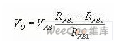


:
Realization of buck structure of LED lighting technology knowledge
3 times
Window._bd_share_config = { "common": { "bdSnsKey": {}, "bdText": "", "bdMini": "2", "bdMiniList": false, "bdPic": "", "bdStyle": " 0", "bdSize": "24" }, "share": {}, "image": { "viewList": ["qzone", "tsina", "tqq", "renren", "weixin"], "viewText": "Share to:", "viewSize": "16" }, "selectShare": { "bdContainerClass": null, "bdSelectMiniList": ["qzone", "tsina", "tqq", "renren" , "weixin"] } }; with (document) 0[(getElementsByTagName('head')[0] || body).appendChild(createElement('script')).src = 'http://bdimg.share. Baidu.com/static/api/js/share.js?v=89860593.js?cdnversion=' + ~(-new Date() / 36e5)];