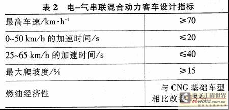
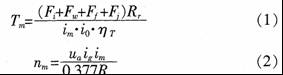
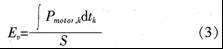
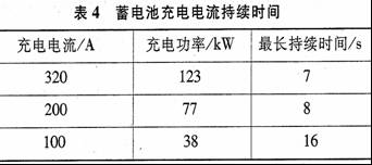
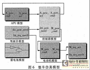
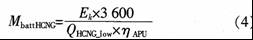
1 Introduction This article refers to the address: http://    With the energy crisis and environmental pollution problems becoming more and more serious, in the past 10 years, various auto manufacturers around the world have launched various types of electric vehicles. Hybrid vehicle technology, as a new automotive technology that can effectively reduce vehicle energy consumption and emissions in the short term, has become one of the research focus of the world automotive industry. China's Ministry of Science and Technology regards it as the content of the 863 major special project of the "10th Five-Year Plan". At present, hybrid electric vehicle products have entered the national announcement procedure and initially have industrialization conditions. The electric-gas series hybrid vehicle combines the advantages of hybrid and natural gas vehicles to further improve vehicle fuel economy and emissions.    Based on the analysis of the driving cycle of the electric one-gas hybrid electric bus running target, this paper designs the power system to ensure the fuel economy of the vehicle under the premise of meeting the vehicle dynamic requirements. 2 Electric-gas series hybrid bus complete vehicle parameters and technical indicators    The basic model of the electric one-gas series hybrid bus studied is a two-step city bus with a length of 11.4 m. The vehicle parameters are listed in Table 1. 3 Hybrid power system structure    At present, the structure of the hybrid electric vehicle power system is mainly divided into three types: series type, parallel type and hybrid type. Because urban buses often work under low driving speeds and frequent starts and stops, it is more suitable to use a series hybrid system to keep the engine running in the optimal working area, reducing engine fuel consumption and emissions. At the same time, series hybrid vehicles are more conducive to recovery of braking energy due to the higher motor power [5]. Therefore, the hybrid electric bus studied in this paper uses the series power system shown in Figure 1.    The engine chosen by the institute is a compressed natural gas engine, and the fuel uses hydrogen-hydrogenated natural gas (HONG) for better emissions. The generator selects an AC synchronous generator. The motor selects the AC motor and is connected to the DC bus via a motor controller. The APU (Power Auxiliary Unit) is composed of an engine, a generator and a rectifier, and the power is output or turned off according to the command of the vehicle controller. The battery is directly connected in parallel on the DC bus to compensate for the difference between the APU output power and the motor input power, and to absorb the feedback braking energy during the braking process. The battery selects a nickel-metal hydride battery. 4 Component selection calculation based on urban bus driving cycle analysis    Compared with traditional internal combustion engine vehicles, the energy economy of hybrid vehicles is more susceptible to different driving cycles. Therefore, it is necessary to select a driving cycle that better reflects the actual operating conditions of the vehicle. This paper is based on the research results of the “863†project “China's typical urban driving conditions†undertaken by the China Automotive Technology and Research Center, and the selection of parts and components.    The component parameters of the HONG hybrid bus are mainly based on the needs of the city bus driving cycle. Figure 2 shows the working condition data of the city bus driving cycle. The total cycle running time is 1304s, the driving range is 5.840km, and the maximum speed is 60km/h. 4.1 Motor parameter selection    According to the speed of the city bus driving cycle and the relevant parameters of the vehicle, the working conditions of the motor drive and brake can be calculated by the following formula (Figure 3):    Where, Tm is the motor torque, N·m; nm is the motor speed, r/min; Fi, Fw, Fj are the vehicle's slope resistance, air resistance, rolling resistance and acceleration resistance, respectively; N; Rr is the wheel rolling Radius, m; ig, io are the speed ratio of the transmission and the final drive; ηT is the transmission efficiency.    Select the motor speed below 2000r/min, the constant torque of 720 N·m and the motor speed above 2 000 r/min. The 150 kW constant power line envelops the operating point in Figure 3. The external characteristics of the motor can be selected accordingly. parameter.    The motor drive torque and power response speed can also be obtained by calculating the motor operating condition point. Urban bus cycle requirements: the torque rise speed of the motor is not lower than 566N·m/s, the falling speed is not lower than 588N·m/s; the motor drive power rising speed is not lower than 104kW/s, and the falling speed is not lower than 128kW/ s,,    For the selection of the high-efficiency area of ​​the motor, the concept of the average driving energy is introduced, that is, the driving energy of the motor in a certain working area within the unit mileage:    In the formula, Ev is the average driving energy kJ/km; Pmotor, k is the driving energy of the motor in each region, kJ; S is the driving distance of the motor in each region, km.    The average driving energy of the motor in each working area is calculated as shown in Fig. 4.    According to the calculated average driving energy of the motor in each working area, an electric motor having a higher driving efficiency in a region with a higher average driving energy is selected, thereby improving motor driving efficiency and overall vehicle economy in the entire cycle.    In the same way, according to the needs of the city bus driving cycle and braking energy feedback, the corresponding parameters of the motor braking state can be selected. After calculation, Zhuzhou Institute's JD14X2 AC asynchronous motor was selected, its rated power is 100kW, the peak power is 150kW, and the torque is 1000 N·m when the speed is below 1000 r/min, in order to improve the climbing performance and acceleration performance of the whole vehicle. Leave a margin.    4.2 APU parameter selection    The economics and emissions of the APU directly determine the economy and emissions of the vehicle. Since the APU is not directly mechanically connected to the transmission system, the operating speed of the APU can be freely selected, and only the power generation of the APU can be selected. Assuming that the electric energy required by the motor is all provided by the APU, the calculated distribution of the generated energy of different APU power generation power segments is shown in Fig. 5. The average power generation of the APU (the total power generation of the cycle divided by the total time of the cyclic drive process) is 38.9 kW. . As can be seen from Figure 5, most of the power generation energy of the APU is distributed in the power range of 2070 kW. Since the power generated by the APU is stored and stored in the battery and is an inefficient process, the power generated by the APU should be directly supplied to the motor drive. This requires the APU to be in the higher energy distribution range (20 to 70 kW) in Figure 5. The power generation efficiency is as high as possible and the emissions are good.    This article selects the 4CT180 CNC engine with UC224G three-phase AC synchronous generator. The rated power of the generator at 1500 r/min is 68 kW; the rated power at 1800 r/min is 78 kW. It adopts three-phase full-wave uncontrollable rectifier with a power range of 10 to 120 kW.    4.3 Battery parameter selection    Assuming that the APU constantly emits an average power generation of 38.9 kW and the other parts are replenished by the battery, the maximum discharge current and duration of the battery can be calculated. After calculation, the maximum discharge current of the battery is 332.7A, and the maximum discharge power is 127.8kW. The duration of each discharge current is as listed in Table 3.    Since the maximum feedback power of the motor is 150kW, the charging power of the battery is about 135kW, and the charging current is 351A. If the feedback braking ability of the motor is maximized during the braking process, the calculated maximum charging current and duration of the battery are shown in Table 4. Column.    According to the data in Table 3 and Table 4, the 80Ah Ni-MH battery developed by the Nonferrous Metal Research Institute was selected. Its rated voltage is 384V. The short-time maximum discharge current and maximum charging current basically meet the demand. 5 vehicle simulation verification    In order to verify the selection of each component, a vehicle simulation model was established, as shown in Figure 6. The power required by the motor is calculated by the city bus driving cycle and transmitted to the vehicle controller. The vehicle controller determines the energy distribution between the APU and the battery. The motor according to the actual received command and the actual power of the APU and the battery. The actual output torque is calculated and transmitted to the chassis-road model to calculate the vehicle speed.    Through simulation calculation, the maximum vehicle speed of the vehicle is ≥70km/h, the acceleration time of 0~50km/h is 16.7s, the maximum grade is 22%, and the vehicle dynamics meet the requirements of technical indicators. Figure 7 shows the simulated acceleration process of the hybrid bus.    The economics of the whole vehicle is verified by the operation of the urban bus cycle to select the optimal control strategy combining the switch type and the power follow-up type, so that the vehicle simulation can continuously run five city bus cycles, and the fuel consumption of the whole vehicle and the SOC value of the battery are changed. As shown in Figure 8.    After 5 operating cycles, a total of 7.47 kg of fuel was consumed, and the SOC value decreased from 80% to 66%. For the amount of change in battery power, use the following formula to convert to fuel consumption:    In the formula, MbattHCNG is the equivalent fuel consumption, kg; Ek is the consumed electricity, kW·h; QHCNGIow is the low calorific value of HONG, J/9; ηAM is the average power generation efficiency of APU.    According to the formula, the reduced SOC value is converted into fuel, and the fuel consumption is 8.20 kg after 5 working conditions, and the fuel consumption is equivalent to 28.1 kg.    The fuel consumption per 100 km of the CNG basic model is 33.2 kg, and the hybrid city bus saves 15.4% of fuel compared with the basic model, meeting the requirements of technical indicators.    At present, the test of the emission performance of the traditional large passenger cars mainly adopts the engine working condition method. The series hybrid bus is driven by an electric motor, and the engine and the transmission system are not directly mechanically connected, so the working area of ​​the engine can be greatly improved. According to the simulation analysis, in the urban bus driving cycle, the engine idle time can be shortened to 10% of the traditional car, and the engine mainly works in the high-efficiency area of ​​1200-1500r/min, avoiding the low load and high load conditions. Operation, so its HC and CO emissions are significantly lower than the base model. 6 Conclusion    This paper introduces a method for designing a hybrid electric bus based on driving cycle. Through the city bus driving cycle data and the vehicle's established parameters, the parameters of the main components (motor, APU, battery) of the vehicle's power system are calculated, which provides a basis for component selection. The vehicle simulation model was established, and the selection results of the vehicle parts were simulated and verified. The simulation results show that the selected components can meet the technical requirements of the vehicle's power economy and the needs of the city bus driving cycle.
Kara offers a wide range of illuminated and non-illuminated Rocker Switches.Ranging from 1 to 6 poles,4VA to 30 amp,with many styles of colors and functions,especially the switches with High-Current used very widely in the welding machines. Certifications include UL, CSA, TUV, CE, and more. Kara Rocker Switches include the KR1-Series abd KR2- Series based on different size of the panel cut-out.
Rocker Switch,Waterproof Rocker Switch,Rocker Switch 3 Pin,Rocker Switch 4 Pin Ningbo Kara Electronic Co.,Ltd. , https://www.kara-switch.com