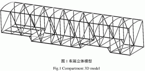
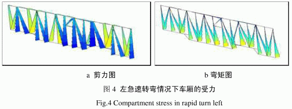
The analysis of static dynamic strength and structural stiffness by finite element method is a necessary means for the design of modern automobile industry. Using modern finite element structural analysis technology, the analysis of automobile structure is no longer only based on experience, and the parameters of the design (such as the structural form of the truss car, the geometrical dimensions of the components and their arrangement), and the structural response (such as The relationship between the output stress and the displacement) can also be used to observe the results of the computational analysis in real time using the visualization technology provided by the software, and the information can be used to optimize the structure. This article refers to the address: http:// This paper mainly discusses how to study the corresponding load and the typical situation of the car in the actual operation, such as uniform speed, emergency braking and rapid turning, based on the finite element model of the truss-type semi-trailer truck. The implementation method of boundary constraint conditions is applied to analyze the stress distribution of the body structure, and the strength and stiffness analysis and evaluation results are given. 1 finite element model establishment The truss type semi-trailer carriage is three-axis, and its structure is shown in Figure 1. Since the car is bilaterally symmetrical, the model is simplified for the convenience of model analysis, and only the left side of the car is selected for simulation analysis. According to the truss structure of the car, it is determined that the car model is established by using the 2-node line unit. Since the car is fixed on the trailer, the place where the car floor and the trailer frame are connected is defined as a fixed point, and the car as a whole is truss type. The structure is welded by steel pipe. The steel pipe material is made of A3 steel with a diameter of 60mm and a wall thickness of 8mm. The material properties are shown in Table 1. 2 Simulation analysis 2.1 Uniform driving situation When the car is traveling at a constant speed, the vehicle speed is higher and the dynamic load is the largest. The reaction force of the road surface causes the car to bear a symmetrical vertical load, which causes the car to bend and deform. The size depends on the static load and vertical acceleration acting on the body. It is required that the car must have sufficient strength and fatigue resistance. The force condition of the carriage under constant driving conditions is shown in Figure 2. a shear diagram b bending moment diagram Figure 2 The force of the carriage under constant speed driving It can be clearly seen from Fig. 2 that in this case, the shearing force of the car is mainly concentrated at the boundary between the diagonal bar and the diagonal bar; the bending moment of the car is mainly concentrated on the diagonal bar, and the diagonal bar is the main bending moment. The bearing body; the axial force of the carriage is gradually increased from the top to the bottom, and the axial force is maximized at the joint of the lower rod and the rod. This is because in the case of uniform straight-line driving, the force of the car is mainly affected by its own weight. Since the straight line travels at a constant speed, the deformation of the transverse rod and the diagonal rod is mainly affected by gravity, and the central portion of the rod has a downward trend, so the bending moment of the central portion is the largest; the lower the axial force is, the more The superposition of dynamic loads is caused, especially at the joint of the rod and the rod, which is superimposed more and reaches a maximum at the lower part of the side pillar. 2.2 Emergency braking situation The emergency braking behavior encountered in the event of an emergency during the driving of the car will cause the car compartment to be subjected to the longitudinal inertial force in addition to the gravity of the various components, and the force condition of the car in the case of emergency braking is as follows. Figure 3 shows. It can be seen from Fig. 3 that in the case of emergency braking, the stress of the car is mainly concentrated on the welding of the rod and the rod, and each welding point is the place with the greatest force. Because under the action of the inertial force, the interaction force between the internal parts of the car is applied to the rod through the welding point, and each rod is fixed at the two ends and welded together, so the various stresses are They are concentrated in these welds. Although the stress at the weld is concentrated and the force is large, the elastic deformation is small and does not affect the overall performance of the cabin. 2.3 Rapid turn situation Under the rapid turning condition, the main consideration is the influence of the inertial force on the vehicle body when the car is turning at the maximum steering acceleration of 0.4g. Due to the sharp turn of the left and right, the lateral inertial force of the car is equal and opposite. Only one situation can be analyzed. Here, the force of the car in the case of a sharp left turn is selected for analysis. The force condition of the carriage in the case of a sharp left turn is shown in Figure 4. As can be seen from Fig. 4, when the car is making a sharp left turn, it is affected by the lateral inertial force directed toward the turning center, and the car body is elastically deformed. Since the underside of the car is fixed, the car is deformed from bottom to top. In the case of a sharp left turn, the stress of the car is mainly concentrated at the bottom end of the bar, that is, the weld between the car and the car body. This is because the car is fixed in the left corner, the bottom end of the car body is fixed, and the upper part is free, so the car body is deformed from bottom to top, and the inertial force of the bar member is concentrated on the fixed end of the bottom end of the bar member. 3 Conclusion In the three basic cases, the elastic deformation of the car is not large, and some even do not deform substantially, indicating that the car can withstand the load under normal conditions. In terms of material selection, it is possible to increase the number of rods or to use thinner and stronger materials without increasing the overall quality. This will not reduce the structural strength of the compartment, but also disperse the stress and relieve the excessive stress concentration. Case.
As printed circuit board technology has continued to evolve, it has paved the way for the creation of a host of exciting product innovations. A prime example is the development of the PCB for LED lighting. The LED is soldered to the circuit board and features a chip that produces the light when electrically connected. A thermal heat sink and a ceramic base are used to bond the chip.
PCB = printed circuit board and PCBA = printed circuit board assembly. For PCB, it means the copper circuits be printed on a board, and so the main composition of PCB are copper and board.
The copper is the circuits material and the circuits designed by the PCB designers. Depends on the current in the circuits, the PCB copper thickness could be done with 0.5oz-10oz. But the PCB designers need be noted that the copper track width/space need be enlarged with the thickness. For example, the minimum copper track width/space could be 3mil/3mil with 0.5oz, but would be 4mil/4mil with 1oz.
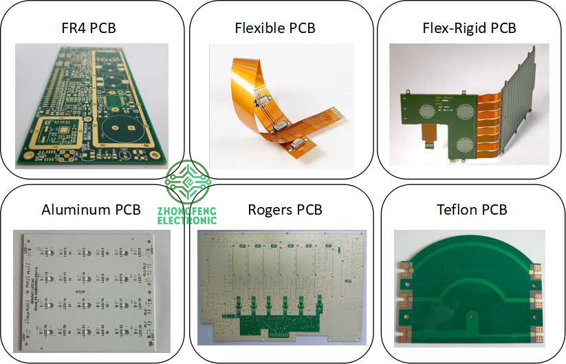
The PCB board could be rigid PCB, could be flex PCB and also could be Flex-Rigid PCB. And the materials could be FR4, PI, Aluminum, Copper-based, Rogers, Teflon, etc. They have different applications. For example, FR4 PCB is the most commonly used for rigid PCB and almost good for all electronics products; PI is the most commonly used for flex PCB; Aluminum and copper-based have good thermal diffusivity and always used for LED PCB ; Rogers PCB and Teflon PCB are always used for High Frequency PCB, etc.
We are the one-stop shop for all kinds of PCB manufacture service from PCB Prototype to big volume, which could save our customers a lot of time and money.
PCB Manufacture Capabilities
Features
Capabilities
Layers
1-36 layers
Material
FR-4, Aluminum, Copper, Polyimide, high frequency (Rogers, PTEE, PI), etc.
PCB Type
FR-4 Standard PCB , Aluminum PCB, Copper-based PCB, HDI PCB , Rigid-Flex PCB, Flex PCB, Thick Copper PCB and Rogers PCB, etc.
Board Thickness
0.1mm-6.0mm
Copper Thickness
1/2oz-6oz(18um-210um)
Biggest Board size
600mm*1200mm
Min Tracing/Spacing
0.075mm/0.075mm (3mil/3mil)
Min drilling Hole diameter
0.15mm(6mil), 0.1mm(4mil)-laser drill
Solder Mask
Green, Black, White, Red, Yellow, Blue and Purple, etc.
Silkscreen color
White, Blue, Black, Red, Yellow
Surface finish
HASL Lead free, Immersion Gold (ENIG), Immersion Tin, Immersion Silver, OSP, Carbon oil, etc.
Special Techniques
Impedance Control, Gold Fingers, Blind/Buried vias, Peelable solder mask, Half holes, Via-in-Pad and Countersink hole, etc.
PCB Products Show
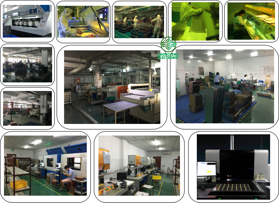
PCB Factory Show
LED PCB LED PCB,LED PCB Board,Aluminum LED PCB Assembly,LED PCB Strip ZhongFeng Electronic Technology Co., Limited , https://www.dopcba.com


An LED PCB Board tends to generate a high volume of heat, making it difficult to cool via traditional means. Consequently, metal core PCBs are frequently chosen for LED application due to their enhanced ability to dissipate heat. Aluminum in particular is often used to manufacture circuit boards for LED lights. The Aluminum PCB typically includes a thin layer of thermally conductive dielectric material that can transfer and dissipate the heat with much greater efficiency than a traditional rigid PCB.

