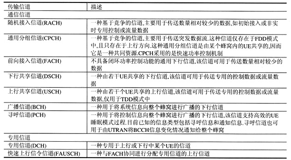
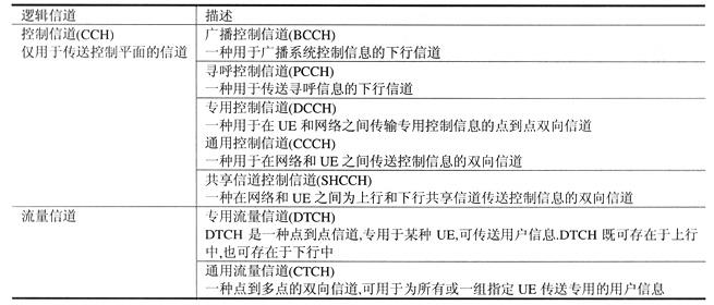
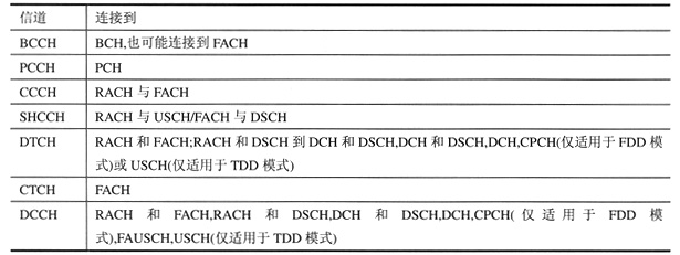
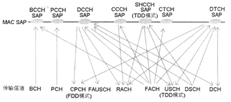
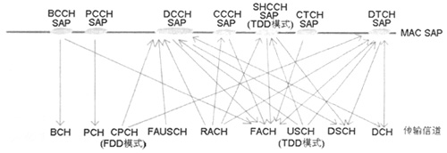
Abstract The wireless interface protocol is mainly used to establish, modify and release wireless bearer services on the UTRA platform. This paper gives the UMTS radio interface protocol structure, and analyzes the services and functions in the physical layer and link layer, PDCP services and functions, broadcast and multicast control services and functions, Uu sublayer services and functions in the network layer, and wireless resources Control (RRC) function. 1. Agreement structure The wireless interface protocol is mainly used to establish, modify and release wireless bearer services on the UTRA platform. These protocols contain related functions at layers 1 to 3, using the term OSI (Open System Interconnection). These three layers are the physical layer (L1), link layer (L2), and network layer (L3). At the same time, the link layer (L2) contains the following sublayers: media access control (MAC), radio link control (RLC), packet data concentration protocol (PDCP), and broadcast and multicast control (BMC). Layer 3 (L3) and the RLC sublayer are composed of the control plane (C plane) and the user plane (U plane). PCDP and BMC only exist in the user plane. Layer 3 contains sublayers in the C plane. The lowest sublayer is Radio Resource Control (RRC), which is connected to Layer 2 through an interface and terminates in UTRAN. The next sublayer provides a copy avoidance function and terminates at the CN. This sub-layer is a part of the access layer and is mainly used to provide access layer services for higher layers. However, we usually assume that it does not belong to the non-access layer. These high-level signaling include mobility management (MM) and call control (CC). In the architecture diagram (see Figure 1), each module represents an instance of its own protocol. At the interface between the sub-layers, we use ellipses to represent service access points (SAP), which can be used for peer-to-peer communication. The SAP between the MAC layer and the physical layer can provide a transmission channel, and the SAP between the RLC sublayer and the MAC layer can provide a logical channel. On the C plane, General Control (GC) uses Notification (Nt) SAP and Dedicated Control (DC) SAP to define the interface between replication avoidance and higher L3 sublayers (call control and mobility management). Figure 1 Wireless interface protocol architecture (the ellipse represents the service access point) Figure 1 also shows the connections between RRC and MAC and between RRC and L1. These connections can provide local inter-layer control services. At the same time, we use the same interface control mechanism between RRC and RLC sublayers, RRC and PDCP sublayers, and between RRC and BMC sublayers. These interfaces support RRC to control the low-level configuration. Therefore, there is a defined discrete control SAP between RRC and each lower layer (PDCP, RLC, MAC and L1). The RLC sublayer combined with practical wireless transmission technology can provide ARQ (Automatic Request Retransmission) function. In this case, we cannot distinguish between RLC instances in the C-plane and U-plane. When the Iu connection point does not change, the CN may request full data protection from UTRAN. However, when the Iu connection point changes (such as SRNS relocation, improvement, etc.), UTRAN may not be able to guarantee full data protection, which ultimately depends on the replication avoidance functional entity in the CN. 2. Business and function 2.1 Business and functions in the physical layer In principle, we can divide the transmission channels of the physical layer into two categories: general channels and dedicated channels (see Table 1). The first type has the UE's in-band identification function when it relates to a certain type of UE. The second type of dedicated physical channel identifies the UE, namely the code and frequency in FDD mode, and the code, time slot and frequency in TDD mode. Table 1 Summary of transmission channels When each transmission channel (except FAUSCH) has a fixed or slow rate of change, a related transmission format is obtained, or when the transmission channel has a fast rate of change, a related set of transmission formats is obtained. We define the transmission channel as a combination of coding, interleaving, and bit rate, and map it onto the physical channel. We define the transmission format set as a set of transmission formats. In a transmission format set environment, a DCH with a variable rate contains a set of transmission formats, that is, each rate corresponds to a transmission format, while a fixed rate DCH has only a single transmission format. 2.2 Services and functions in the link layer Business and functional characteristics in the MAC layer: (1) Data transmission: No segmentation is required to provide unacknowledged transmission for MAC layer SDUs between peer MAC entities. (2) Redistribution of wireless resources and MAC parameters: According to RRC requests, the functions of wireless resource allocation and MAC parameter changes are performed. In addition, in the TDD mode, the MAC can allocate resources in an autonomous manner. (3) Measurement result report: report local measurement results, such as data flow and quality indication to RRC. The MAC layer can provide data transmission services on logical channels. We divide logical channels into two categories: control channels for control plane information transmission and traffic channels for user plane information transmission (see Table 2). Table 3 shows the connection relationship between logical channels and transmission channels. Table 2 Summary of logical channels Table 3 Connection relationship between logical channel and transmission channel Figures 2 and 3 show the mapping relationship between transport channels and logical channels in FDD and TDD modes from the UE side and the UTRAN side, respectively. Figure 2 See the mapping relationship between logical channels and transmission channels from the UE side Figure 3 from the UTRAN side to see the mapping relationship between logical channels and transport channels 2.3PDCP business and function The Packet Data Centralization Protocol (PDCP) service can provide transmission and reception of network PDUs in acknowledgment / non-acknowledgement and transparent RLC modes. As part of the PDCP function, it first maps network PDUs from a certain network protocol to a certain RLC entity. Secondly, it compresses the redundant network PDU control information at the transmitting entity, and decompresses the redundant network PDU control information data at the receiving end (header compression / decompression), and can perform TCP / IP header compression and decompression if necessary. compression. 2.4 Broadcast and multicast control services and functions The BMC can provide broadcast / multicast transmission services for general user data in a transparent or unacknowledged manner on the user plane on the wireless interface. Its functions mainly include: (1) Store cellular broadcast messages: store messages received through the CBC-RNC interface for scheduled transmission. (2) Traffic monitoring and radio resource request for CBS: On the UTRAN side, based on the message received from the CBC-RNC interface, BMC calculates the required transmission rate for the cellular broadcast service and requests the appropriate CTCH / FACH resource from RRC . (3) Scheduling of BMC messages: BMC receives scheduling messages and broadcast messages of each cell through the CBC-RNC interface. Based on the UTRAN scheduling information, the BMC generates scheduling messages and schedules the BMC message sequence accordingly. On the UE side, the BMC calculates scheduling messages and publishes scheduling parameters to RRC. For the case of CBS discontinuous reception, RRC can use these parameters to configure the lower layers. (4) Transmit the BMC message to the UE: According to the scheduling message, transmit the BMC message (scheduling message and cellular broadcast message) to the UE. (5) Transmit the cellular broadcast message to the upper layer (NAS): On the UE side, the received cellular broadcast message is accurately transmitted to the upper layer (NAS). In this process, the corrupted message is not transmitted. 2.5 Uu sub-layer services and functions in the network layer The main Uu sub-layer services include general control, notification and dedicated control. General control provides a general information broadcasting service for all UEs in a geographical area. The notification service can provide paging and notification broadcast services for specific UEs in a certain geographic area. The dedicated control can provide service support for connection establishment / release and message transmission using the connection. It is also possible to transfer information during the connection establishment phase. 2.6 Radio Resource Control (RRC) function The RRC layer can handle layer 3 control plane signaling between UT and UTRAN. Its main functions include: (1) Broadcast the information provided by the access layer and non-access layer (core network). The RRC functional entity can transmit information from the network to all UEs in the form of broadcast. System information is usually repeated regularly. (2) The establishment, re-establishment, maintenance and release of RRC connection between UE and UTRAN. The upper layer requests the UE to establish the first signaling connection for the UE. RRC connection establishment includes optional cellular reselection, access control, and layer 2 signaling link establishment. (3) Establishment, reconfiguration and release of radio bearers. According to the demand from higher layers, the RRC functional entity can complete the establishment, reconfiguration and release of radio bearers in the user plane. (4) Allocation, reconfiguration and release of radio resources in RRC connections. The RRC functional entity can complete the radio resource allocation (such as code and CPCH channel) required by the RRC connection, including the needs from the control plane and user plane. (5) RRC connection mobility function. During RRC connection establishment, RRC connection mobility-related evaluation, decision-making, and execution functions can be completed, such as performing handover, inter-system handover preparation, cell reselection, and cell / paging area update processes based on UE completion measurement results. (6) Paging / Notification. When necessary, when a request from a higher layer is received on the network side, paging information can be broadcasted from the network to the selected UE, or a call can be initiated during RRC connection establishment. (7) High-level PDU routing. The high-level PDU on the UE side is routed to the correct high-level entity on the UTRAN side, and finally to the appropriate RANAP entity. (8) Control of required QoS. It can ensure that the QoS required by the wireless bearer is satisfied, if there are enough wireless resources to allocate. (9) UE measurement result report and report control. The RRC can control the measurement results completed by the UE according to what, when, and how to report, and can also control the measurement results of the UMTS air interface and other systems. The RRC layer can report the measurement results to the network by the UE. (10) Outer loop power control. The RRC layer can control the setting of the closed-loop power control target value. (11) Encryption control. Between the UE and UTRAN, the process of setting the encryption function (on / off) is provided. (12) Slow DCA. This function is only applicable to the TDD mode. According to the long-term decision criteria, the RRC functional entity can dynamically allocate high-priority wireless resources. (13) Control of radio resource allocation in the uplink DCH. The broadcast channel is used to send control information for all relevant users, so as to control the rapid radio resource allocation in the uplink DCH. (14) Initial cell selection and new selection in idle mode. According to the measurement results in idle mode and cell selection criteria, select the appropriate cell. (15) Integrity protection. In RRC messages that are sensitive and / or contain third information, add a message authentication code (MAC). (16) Initial configuration for CBS. At the BMC sublayer, the RRC functional entity can be initially configured. (17) Allocate radio resources for CBS. According to the traffic requirements indicated by the BMC, the RRC functional entity may allocate radio resources to the CBS. (18) CBS does not connect to receive configuration. When the UE monitors the resources allocated to the CBS, the RRC functional entity can configure the lower layers (L1 and L2) of the UE. (19) Timing advance control. Control timing advance operation, this function is only applicable to TDD mode. 3. Conclusion The UMTS business component set will continue to evolve, and UMTS applications and business engines will continue to evolve. Therefore, from the perspective of the service provider, it does not matter which industry the user belongs to. Eventually, with the continuous deepening development of mobile services, free Internet and service providers, users will only care about service quality, service charges and application value. The ideal platform for business differentiation is coming soon, and the process of using full 3G capabilities to implement new services will continue.
Battery Regenerator is very popular. More than 75% of the batteries breaking down and losing capacity are sulphated, but can be restored with the right equipment. Our lead-acid Battery Pulse Protector - the most effective Battery Pulse Rejuvenator available for ensuring battery reliability with any-pulse at anytime to maintain and protect your battery. Battery Pulse Protector is a new generation of high-tech environmental protection product with easy installation and maintenance free.
Battery Smart Pulse Protector,Reverse Battery Protection,Battery Protection Methods,Battery Protection Circuit Module Shenzhen Daceen Technology Co., Ltd. , https://www.daceen-sz.com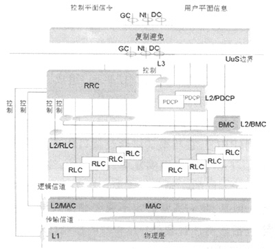
 This battery smart pulse protector utilizes battery energy or float power supply to produce specific electronic pulse successfully removes battery sulphation, to keep the battery always maintain efficient working condition due to a electrical high-frequency pulsation process.
 Battery Pulse Desulfator is a totally automatic battery protecting system that works 24 hours every day to eliminate battery sulphation and keep battery equalization. This revolutionary Battery life Saver saves time, money and effort by reducing battery-related downtime, maintenance and replacement.
Lead-Acid Battery Restoration Solution restore all of Lead Acid Battery(AGM, GEL, VRLA, MF, Flooded, Dry, Traction, Deep cycle and Stationary), Extend battery life up to 1~2 times longer and helps protect the environment by reducing the number of batteries discarded every year.
More than 10 years application in Military, Safety & Stable,Widely Application & Business Partner in Military Vehicles, Gardening Tool, Truck , Bus, Car, Motorcycle, Golf Cart, Forklift , Electric Vehicle, Railway, Ships, Wind & Solar power system, Telecommunication base site, UPS backup power etc.