EconOscillator is a trademark of Maxim Integrated Products, Inc.
Yaxing`s high performance films are resistant to extreme temperature, chemicals&moisture. It was widely used in Chemical storage bags and Chemical resistant liners.
With our specialized equipment and processes we can provide tight tolerances and fast setup services to meet your needs.
Characteristics:
·Excellent chemical stability
·Extremely low friction coefficient
·Good abrasion resistance
·Outstanding Moisture resistant
·Perfect anti-corrosion resistance
Release Film,Bonding Film,Ptfe Membrane,Non Stick Film TAIZHOU YAXING PLASTIC INDUSTRY CO., LTD , https://www.yaxingptfe.com
IntroductionEconOscillators have an internal oscillator that provides a base frequency, and they use a built-in divider chain to lower a base frequency to the desired rate. Each part number can divide down four base frequency rates (60MHz, 66.67MHz, 80MHz, or 100MHz ) for adjustments up to 2052 times slower than the base part frequency. EconOscillators can be used for any type of clocked logic, including microprocessor, FPGA, and CPLD circuits, depending on system requirements.
8051 Microprocessors and RS-232 Serial Communication When selecting a clock, two factors deserve careful consideration: clock rate and clock accuracy over the operational life span. In an 8051 microprocessor system, the use of RS-232 serial communications often determines the system clock rate. Consider, for example, asynchronous mode 1 serial communication using a 12MHz clock (the maximum clock rate for the original 8051). Table 1 shows the timer 1 auto reload values ​​required to establish standard baud rates.
Table 1. Baud Rate and Baud Rate Error Using a 12MHz Crystal for an Original 8051 Timer 1 Auto Reload Value Actual Baud Rate
(Desired Baud Rate) Baud Rate Error 255 31250 (28800) 8.5% 254 15625 (14400) 8.5% 253 10417 (9600) 8.4% 249/250 4464/5208 (4800) 7% / 8.5% 243 2404 (2400) 0.16%
The actual baud rates in Table 1 were calculated using the following formula (reproduced from Dallas Semiconductor's High-Speed ​​Microcontroller User's Guide): 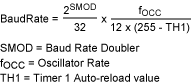
The table numbers are based on these timer 1 conditions: set to increment 12 clock cycles per timer (DS87C520 can increment timer 1 each 4 or 12 clock cycles) auto reload mode enabled baud rate doubler (SMOD = 0) disabled. Most users of RS -232 serial communication agree that any baud rate error over 3% is likely to cause communication errors, which occur in spite of synchronization of the start and stop bits during data transfer. A 3% allowable error limits the maximum communication rate with a 12MHz crystal to 2400 baud—not bad for the early 1990s, but a little slow for today's standards. Luckily, there are crystals that cater to 8051 serial communications: either an 11.059MHz or 22.118MHz crystal. Microprocessors using these crystals see a considerable improvement in baud rate (Table 2), achieving data transfer rates up to 57.6 kbps (115.2 kbps with a DS87C520 using the baud rate doubler, SMOD = 1), which is respectable for most of today's microprocessor systems.
Table 2. Baud Rates Generated Using Crystal Frequencies Selected for RS-232 Serial Timer 1 Auto-Reload Value Baud Rate with
Focc = 11.059MHz Baud Rate with
Focc = 22.118MHz 255 28.799.5 57598.9 254 14399.7 28799.5 253 9599.8 19199.6 250 4799.91 9599.83 244 2,399.95 4799.91 232 1199.98 2,399.95 208 599.98 1199.98 160 299.99 599.99 64 149.99 299.99
Note:
Requiring the baud rate to be within 3% of the specified rate also places an accuracy requirement upon your clock. Even with an ideal clock rate selected for RS-232 communication, if the clock varies more than 3%, you may not be able to communicate consistently.
Using the DS1077 EconOscillator to Clock an 8051 Microprocessor The DS1077 comes in various base varieties, with the internal oscillators running at 133, 125, 120, 100, and 66.667MHz. Using the internal divider chain to slow them down enough for an 8051 application, in theory any of these parts could be used. However, if you plan to use the serial port of your 8051, you should select the base part that best fits your microprocessor's needs, depending on both the baud rate required and baud rate generation formula provided with your microprocessor.
In the case of the 8051 microprocessor in our example, oscillator frequencies of 11.059MHz and 22.118MHz were desirable, and an approximately 3% error rate was tolerable for baud rate generation. If you use the 66.667MHz base part (DS1077-66), you would be able to divide the base frequency by six (6) down to 11.111MHz. This has a small error from the ideal frequency of 11.059MHz (0.47%), and the error remains acceptably low even with a worst-case deviation of 1.25% from the programmed frequency. Thus, the DS1077-66 allows a maximum error of 1.72% from the desired frequency of 11.059MHz, which is adequate for communication at rates up to 28.8kbps.
If you are using an 8051 with a higher allowable clock rate such as the DS87C520 (33MHz maximum clock rate), you could simply divide the clock rate by three to 22.222MHz. The maximum error is still fine for communication at any of the 22.118MHz baud rates. The higher clock rate also provides a higher level of processor performance for your other application needs.
The big advantage in using the DS1077 for an 8051 design is flexibility. A design that started out using an original or equivalent 8051 microprocessor (12MHz maximum clock rate) can be simply upgraded by reprogramming the oscillator and replacing the microprocessor. Depending on the design, you may even be able to reprogram the DS1077 in-socket. If you are using the 40-pin DIP version of the 8051 microprocessor, Maxim and many other companies make several 100% compatible replacement chips. The fastest of them all, Maxim's DS89C430, offers a 50x performance increase over the original 8051 design, and has several resources available, including watch-dog timers and power management, that were not available on the original 8051. Other chips, such as the DS87C520, can provide up to an 11x- performance increase. (Maxim also makes other versions of the 8051 that have PWM and ADCs for control applications, but they are not available in the 40-pin DIP package.)
Hardware SetupTo use the DS1077, you will need to establish a way to program its EEPROM registers. Once the DS1077 is programmed, the schematic shown in Figure 1 shows how to wire the DS1077 for proper operation with an 8051 microprocessor. Note that the output of the DS1077 goes into XTAL1, and XTAL2 is not connected. XTAL2 is normally the crystal oscillator output of the 8051. Connecting anything to this pin will just load the microprocessor down, which is not necessary when any auxiliary clocked device can be connected in parallel with the microprocessor on XTAL1. (This is assuming that the joint loading of the auxiliary device and the 8051 does not exceed the output current specification of the DS1077.) 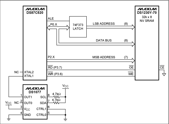
Figure 1. Hardware Setup for Using a DS1077 Oscillator to Clock an 8051 Microprocessor.


Using a EconOscillator to Cloc
Abstract: When using an 8051-based microcontroller, care must be taken in selecTIng an external clock reference to ensure that the TIming requirements the controller's serial interface are met. Typically, the 8051 serial port is used with an RS-232 transmitter / receiver to provide a serial communicaTIon link to another processor or host processor. The RS-232 specificaTIon has specific timing requirements, which must be met to guarantee communication to all other devices using this protocol. 8051-based processors generate their serial port timing using a combination of external timing reference (crystal or clock) and internal programmable divider chains. This application note demonstrates how the external clock requirements can be met using an EconOscillator and provides calculation assistance in programming the 8051 internal serial port control registers.