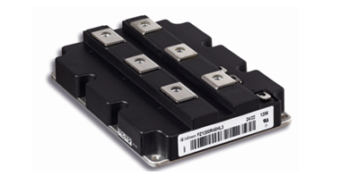
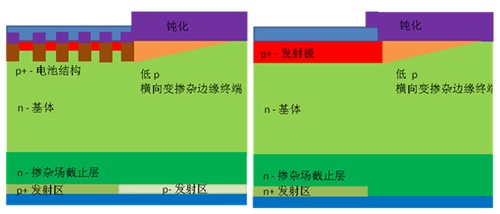
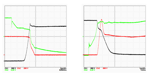
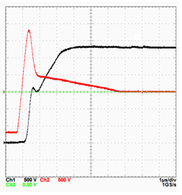
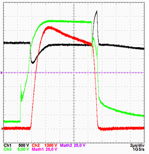
Manufacturers have developed new 4.5kV insulated gate bipolar transistor (IGBT)/diode chipsets for high voltage direct current (HVDC) applications and optimized their performance. This chipset is characterized by very low turn-on voltage loss, high current, high voltage fast turn-on behavior and high robust short-circuit behavior. High robustness can be achieved by applying HDR technology to IGBTs and diodes. The emergence of the 4.5kV-class chipset is a reinforcement of the existing 3.3kV and 6.5kV high-voltage chipset products. The chipset is available in two different housings: The first chipset features a highly insulated 6.5kV module housing that provides 10.2kV isolation and a creepage and clearance distance to withstand the harsh environment of traction applications with 2500-3000V DC bus voltage. The second chipset was designed for the IHV-B housing and is the successor to the well-known IHV-A modules that are used around the world. The module is suitable for use in industrial applications such as medium voltage drives and various high voltage direct current (HVDC) applications, as well as in flexible AC transmission systems (FACTS) applications. See Figure 1 for the module. Figure 1: Package of the 4.5kV FZ1200R45HL3 module For future HVDC systems – These IGBT-based voltage source converters (VSCs) will play an important role in future HVDC systems compared to the well-known thyristor-based grid-connected high-voltage DC transmission. The IGBT-based solution relies on independent active current and reactive current control, which is achieved by the turn-on and turn-off functions of the IGBT. In addition, they have demonstrated superior performance in dealing with AC grid failures. In the field of high voltage applications, it is necessary to connect a large number of semiconductors in series, and it is necessary to ensure a high-precision synchronous switch. To better meet such demanding design requirements, multi-level VSC - Modular Multilevel Converter (MMC) is recommended for high voltage applications such as HVDC and FACTS. In HVDC applications, the switching frequency of a single IGBT module can be reduced. Therefore, the effect of low on-state losses on reducing overall power consumption is of particular interest. IGBT and diode structure The IGBT trench technology has low on-state losses because of the carrier accumulation between cells, cell pitch and channel length are optimized, and there is a channel width designed for high blocking voltage. Therefore, trench technology provides a viable solution to the cell's download stream concentration and has a wider range of influence than standard planar technology. Figure 2 depicts a cross-sectional view of a 4.5KV IGBT/diode. Both devices use a VLD structure (lateral doping) for edge termination. This structure, combined with the vertical HDR structure, reduces the dynamic avalanche during the switching sequence, giving the IGBT a very high turn-off robustness, giving the diode a very high rectification robustness. Figure 2: Cross-sectional view of IGBT (left) and EC diode (right) for HDR and VLD edge termination Electrical performance 1) Static characteristics In order to achieve a lower on-state voltage of the 4.5KV IGBT, the well-known 6.5KV device platform trench technology was specifically adjusted. The choice is to use a suitable matrix material and use an adjusted field stop and optimized battery design to give the best-in-class on-state characteristics of 4.5kV devices. Based on the nominal current of 1200A of the FZ1200R45HL3 module, a typical VCE(sat)=2.35 V@25°C, VCE(sat)=2.9V@125°C and VCE(sat)=3.0V@150°C are obtained. The EC diode exhibits an almost neutral temperature coefficient at a current equal to 1200A nominal current, exhibiting a typical forward voltage drop over a temperature range of 25 ° C ≤ T ≤ 150 ° C and Vf ≤ 2.5V. 2) Dynamic characteristics The switching waveforms under rated conditions, ie VCE=2.8kV, IC = 1200A and T=150°C are shown in Figure 3. Under these conditions, a soft turn-off behavior with a commutation inductance of 150 nH can be found. VCE does not exceed 3.4kV. Softer shutdown is also guaranteed under more demanding conditions, with higher stray inductance, higher current, and operating temperatures as low as -40 °C. Typical on and reverse recovery waveforms are also depicted as graphs, which show a very smooth IF tail gradient. Figure 3: Typical wavelength @ 800V / 1200A, 150μH, 150°C Shutdown: VCE=400V/div, IC=150A/div, Rgoff=5.1 W, VGE=5V/div Connected: VCE=350V/div, IC=300 A/div, Rgon=1.2 W, VGE=5V/div Reverse recovery: VCE=500V/div, IC=500A/div, Rgon=1.2 W High voltage and high current switching In HVDC applications, it is important to ensure that the IGBT can exhibit fast turn-on behavior in high voltage, high current conditions in the event of a fault, and the durability of the device under these conditions beyond the RBSOA limits has been evaluated. The channel width is a parameter that the IGBT can use to adjust the turn-on behavior for predictable failure events. The channel width is increased to achieve fast turn-on performance. At the same time, as the channel width increases, the short-circuit current also increases, so it is limited by the short-circuit capability. Therefore, it is necessary to strike a balance between the turn-on performance and the short-circuit capability, or it can also meet the requirements of improving the turn-on performance and enhancing the short-circuit capability by enhancing the vertical structure of the IGBT. 3) Short circuit capability In order to prove the short-circuit capability of the IGBT type 1, a severe condition of VCE=3000V, VGE=17V and T=125°C is applied thereto. The 9500A, which is close to 8 times the nominal current, was successfully turned off. The vertical IGBT structure is optimized to extend the short-circuit time limit until the device fails. Figure 4 shows a short circuit waveform. The short-circuit event can be handled by the IGBT module FZ1200R45HL3, which provides a reliable shutdown even after a short-circuit duration of 10 μs. Figure 4: Short circuit waveform @ 3000V, 125°C, VGE=17 V (VCE=500V/div, IC=1.3kA/div, VGE=10V/div) 4) Robustness of IGBTs and diodes In high-voltage DC applications and traction applications, IGBTs and diodes can increase system reliability with their high overcurrent shutdown capability. With the HDR concept, the impact of the termination system on the robustness of the IGBT is negligible. Only the unit design will constitute a limiting factor. The trench structure allows for further reduction in the source length of the IGBT. Since the current density is inversely proportional to the source length, the latching immunity of the trench IGBT is effectively improved, and excellent turn-off durability is achieved, which is manifested by a current that can switch four times higher than the nominal current. Does not cause severe oscillations in the current or voltage signal. In addition to low on-state voltages, the new 4.5kV EC diodes exhibit low dynamic power and very high robustness. The 200A nominal current module has been tested for diode recovery at Pmax ≥ 4 MW. The test results show that the diode is not damaged. 5) Surge current capability In the event of a fault such as a short circuit in the transmission line, a failure condition such as a high surge current may be encountered during operation of the diode. Therefore, the ability to withstand high surge currents is an important criterion for examining module availability. You can reduce the VF by optimizing the vertical design and apply the HDR concept to get enough surge current immunity. For an IC = 1200A module, the typical IFSM value can be around 10kA, which is equivalent to I2t equal to 500 kA2s at 125°C and I2t equal to approximately 500 kA2s at 150°C. 6) Robustness of cosmic radiation The design of 4.5kV IGBT and emitter control diodes determines their robustness to cosmic radiation. The vertical device structure exhibits low electric field strength at typical DC bus voltages. The typical failure rate (FIT) of the FZ1200R45HL3 module at ~3kV DC bus voltage has been determined, ie the number of failures during the 109 hour operating time is 100 FIT. In addition to blocking the steady state during the DC bus voltage, the cosmic radiation robustness of the switch operation is also taken into account. Simulation experiments have confirmed that the extra dynamic FIT rate at dV/dt ≤ 2kV/μs is negligible because of the limited internal electric field of the device. to sum up The newly introduced 4.5KV trench field stop IGBT and emitter control EC diodes are designed for industrial applications and are especially suitable for high voltage DC applications in IHV-B packages. The IGBTs and diodes have a very low on-state voltage and fast turn-on IGBT switching behavior, making them ideal for use in high voltage, high current environments where conditions are exceeded. At the same time, the FZ1200R45HL3 module also shows excellent short circuit performance. In addition, the overcurrent shutdown test also demonstrates the excellent robustness of IGBTs and diodes. The new device has a maximum design operating temperature of 150 °C. These features are achieved by using HDR technology to adjust the trench cell design and the vertical structure of the 6.5kV IGBT.
Microsoft Surface Charger have 4 types. For Surface Pro 1/2/3/4.
Surface Pro 1/2: 12V 3.6A
Surface Pro 3: 12V 2.58A
Surface Pro 4: 15V 1.6A
Microsoft charger has different connector with other Laptop Adapter. Its connector is magnetic tip.
Definitely Charge Faster, excellent Power Supply for Microsoft Surface Pro. Just drop it in your bag or even pocket and get going – no need to carry anything else, as power is always within easy reach.
Microsoft Surface Charger Microsoft Surface Charger,Microsoft Surface RT Charger,Microsoft Surface Tablet Charger,Charger For Microsoft Surface Shenzhen Waweis Technology Co., Ltd. , https://www.waweis.com