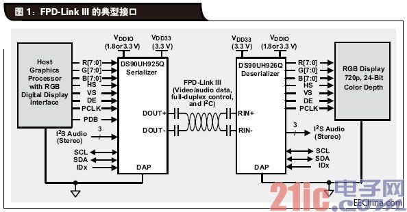
Flat Panel Display Link III (also known as FPD-Link III) is an interface for a wide range of automotive applications for point-to-point video transmission. The interface supports high-definition digital video transmission and bi-directional control channels over low-cost cables (twisted pair or coaxial cable). The FPD-Link III serial deserializer is optimized for both the link between the processor and the display and the link between the processor and the camera (Figure 1). This article will provide an overview of these links and the technological developments they are expected to achieve in the near future and how they can make the most of this technology. This article refers to the address: http:// Not long ago, the camera was still new in the car, mainly used to observe the rear distance of the larger vehicle when reversing, but nowadays it is not surprising to have a reversing camera in a low-cost economy car. With the continuous development of automotive technology, the camera application in the vehicle will be more and more abundant, and the camera itself will become more and more sophisticated. The reversing camera helps the driver to intuitively understand the distance behind the car, but if only the rear view mirror is used, it is inconvenient even if it can be observed. The next step is the surround-view system. In a typical panoramic vision system, four cameras will be installed on the car, one on the front and one on the rear bumper, two on the two sides of the body for rear view. Each camera uses a fisheye lens, which allows you to synthesize a complete image of the condition around the body based on the four images generated. In the panoramic vision system, four fisheye images can be provided to a video image processor such as the Texas Instruments DRA74x "Jacinto 6" for processing. The processor not only eliminates fisheye distortion, adjusts the visible view point, but also combines the four images to create a virtual overhead view of the car, helping the driver to clearly see any obstacles in front of or behind the vehicle. When processing these images, a specific portion of the image is magnified and the rest is compressed. In order to maintain high image quality, the density of the pixels should be higher than the density required by standard visual inspection. The current car image generator supports 1 megapixel (MP) images, and the 2MP image generator is coming soon. To support next-generation image sensors, the new serial deserializer design, optimized for 2MP image generators, is just around the corner for automotive designers. As these video recorders place higher demands on data rates, a new generation of interfaces that support them will also emerge. Another aspect of the evolution of automotive vision systems is that the industry is moving from using single camera systems such as reversing cameras to using multiple cameras. Image generator synchronization has become a critical feature when using multiple cameras. In applications such as panoramic vision applications, the synchronization of all the imagers makes image processing easy. However, in the case of using two cameras to work alternately to create a front 3D stereoscopic image scene, it is also necessary to use synchronization to determine the exact position of the moving object, that is, even to determine the static object seen from the moving vehicle. The exact location. Next-generation systems will have to have the potential to support multiple fully synchronized cameras. In many areas, adding more features to existing technology will make the interconnection more complex and costly. For example, to add write protection to a link between a home DVD player and a video monitor, you need to replace the analog coaxial cable with an HDMI cable. This new connection method not only achieves better picture quality, but also provides write protection. But the price is that you need to use a much higher cost cable/connector ecosystem, and it's also difficult to support longer connections. A similar problem exists in cars, and the EPD-LINK III has been expanded to transmit copyrighted content from Blu-ray players or servers to the rear-seat entertainment display using the same twisted-pair cable. This technical specification can achieve this function without causing an increase in the cost of the medium, and will not shorten the transmission distance of the old-fashioned medium without copyright protection. Figure 1 shows the chipset that embody this technology. In these devices, the same information that was transmitted over a separate conductor in the past is now encoded and transmitted using the FPD-Link III method, which shares the same transmission conductor as the video content. Transferring video from the camera to the processor or transferring the video from the Blu-ray player to the display is only part of the processing. In both cases, it is necessary to transmit control signals from the opposite direction. Specifically for the camera, the processor needs to configure the image generator. For a rear seat entertainment display, the user interface is typically a touch screen and touch commands must be sent back to the processor from the screen. The FPD-Link III can handle this with an integrated return channel that not only allows the same coaxial cable or twisted pair to transmit video in one direction, but also provides independent bidirectional control channels that share the same conductor. This makes it possible to use low-cost cables that are thin and flexible. But there is also a need to address power issues, and both the camera and the monitor require power. Can I use the same cable to power both the device and the communication link? Powered by coaxial cable The key to powering and communicating with the same cable at the same time is the need to think about the frequency domain characteristics of the cable. The video forwarding channel and the bidirectional control channel on the FPD-Link III can share the same cable because the two signals occupy different spaces in the frequency domain. Taking the DS90UB913A-Q1 and DS90UB914A-Q1 as examples, the frequency domain occupied by the control channel varies from approximately 1 MHz to approximately 5 MHz. The frequency domain occupied by video channels ranges from approximately 70 MHz to approximately 700 MHz. Adding power transmission to the same cable must avoid interference with either of the above two bands. For coaxial cable power (POC), a circuit is required to split the input signal into two branches (Figure 2). One of them is responsible for transmitting the DC power supply for the POC circuit, and the other is responsible for transmitting the signal without the DC power supply. To achieve this, a component needs to be placed on the signal path to pass the signals of the return and forwarding channels, but to block the DC. This can be achieved by simply using a capacitor. The 0.1μF capacitor has a very low impedance from 1MHz in the return channel band up to the 700MHz upper limit. The capacitors are available everywhere in the market and are inexpensive. In terms of the parasitic inductance of a 0.1μF capacitor, the 0603 capacitor is around 1nH, which has no effect on the frequency band used. To separate the AC signal from the DC power supply, this size of capacitor is ideal. For the other branch, it is more difficult to pass the DC power supply and avoid interfering with the AC signal. Since the data path passes through the impedance-controlled transmission line, the impedance of the low-pass circuit must be maintained at a high level throughout the frequency band of the forwarding channel. To prevent the power circuit from interfering with the data path, the impedance of the circuit must be approximately 20 times higher than the characteristic impedance of the cable. Taking a 50 Ω coaxial cable as an example, the impedance must be greater than 1 KΩ from 1 MHz to 700 MHz. If you have an ideal conductor, you can use it for this application. Unfortunately, finding the ideal conductor is more difficult than finding the ideal capacitor. To get an impedance of 1k or more on the lower 1MHz band used by the return channel, a 100μH inductor is required. However, typical 100μH inductors have parasitic capacitance that drops below 1k at frequencies above 70MHz. Therefore it will interfere with the forwarding channel. Figure 3 is a plot of the impedance of some different conductors as a function of frequency. Note that the impedance rises first to a specific point where the parasitic capacitance dominates and then falls. As can be seen from the figure, the 100μH conductor can block the control channel well because its impedance is about 1k from 1MHz to 5MHz. However, when the forwarding channel is 150 ΜH ,, the impedance drops to approximately 200. The solution is to use a circuit with two series inductors. One 100μH inductor is used to block the control channel, and the other smaller inductor is used to block the video channel. For the second inductor, an inductance of approximately 5μH is very suitable. The required physical characteristics determine the value of the inductor (100 μH and 4.7 μH), but the actual size is determined by the ability of the core to maintain the magnetic field. Physically speaking, smaller inductors have lower saturation currents. One way to use smaller inductors is to reduce the current demand of the circuit, which can be achieved by increasing the voltage transmitted by the coaxial cable. If the camera requires 1.5W of power and 5V is transmitted over a coaxial cable, the current required is 300mA. The selected 100μH inductor may be the smallest physical size that can be tolerated (7mm x 7mm x 4mm). However, if you use 12V power, you only need 125mA. Inductors that support this lower current are three-quarters smaller in physical space than inductors that support 300mA. in conclusion Video plays an increasingly important role in the modern automotive arena. FPD-Link III is the ideal technology to support today's and tomorrow's needs by minimizing system cost by enabling more features with inexpensive cables. In addition, it is a technology that keeps pace with the times and keeps up with the future. Snow Melting Heating Film is mainly designed to be used in Snow Melting Heat Film for Water pipe,oil pipe,unfreeze PipeGuard heating film .we are a professional and leader Chinese exporter of heat film,Customization options (for example: SMT components, flex cable and connectors) can provide the perfect complete solution that can significantly reduce assembly time and increase productivity.Providing a variety of complex shapes design, and different power designs. Membrane in the same piece electrically heated heating circuit can be designed and holding circuit,we are looking forward to your cooperation. Snow Melting Heat mat for PipeGuard Melting Snow,Melting Ice,Snow Melting Heat Film For Tubing,Water Pipe Snow Melting ShenZhen XingHongChang Electric CO., LTD. , http://www.xhc-heater.com