Automotive Rotary Switch
YESWITCHES Automotive Rotary Switches is a multi-function switch selection switches. This Momentary Rotary Switches is widely used in car modification design, car dimmer, this selector switch can be equipped with handle, built-in beautiful LED indicator design, conspicuous operation indicator
The Features of this type of rotary switch: High current load, 10A 125VAC, 6A 250VAC and 20A14V DC, 10A28V DC; Panel card type installation, multi-position design 6 files (0-5) and 5 files (0-4); High load current rating, simple mounting and beautiful appearance make this rotary switch unanimously recognized by customers in the automotive and electronics industries.
The rotary switches offers more rotary switches for PCB or panel-mount applications. Miniature and subminiature designs save space on PCBs, while solder lug, PC thru-hole, wire lead, or quick connect terminations support a variety of mount options.Applications:All kinds of home appliances products, Industrial electronic equipment.
Automotive Rotary Switch,Waterprof Automotive Rotary Switch,Automotive Rotary Switch Waterproof YESWITCH ELECTRONICS CO., LTD. , https://www.yeswitches.com


The birth and development of the CANopen protocol
The OSI model, standing for Open Systems Interconnection, is a conceptual framework developed by the International Organization for Standardization (ISO) to standardize and structure communication between different computer systems. It divides network communication into seven distinct layers: the physical layer, data link layer, network layer, transport layer, session layer, presentation layer, and application layer. Each layer has specific functions and interacts with the layers above and below it to ensure seamless data transmission.
In the context of the CAN (Controller Area Network) fieldbus, only the first two layers of the OSI model are defined. The physical layer (as specified in ISO 11898-2) deals with the actual hardware and electrical signals, while the data link layer (defined in ISO 11898-1) manages the transfer of data between nodes. These two layers are typically implemented in hardware, meaning that developers don’t need to write software or firmware for them. Instead, they can simply use the provided interfaces and registers to control CAN communication. This is illustrated in Figure 1.
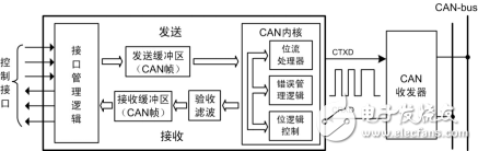
**Figure 1: CAN controller structure**
However, CAN does not define an application layer, which means it doesn't specify how devices should interact or what data they should exchange in real-world applications. This is similar to having raw iron ore (physical layer) processed into iron ingots (data link layer), but without any clear instructions on how to turn those ingots into cars, ships, or other structures. As shown in Figure 2, the application layer is missing in basic CAN implementations.
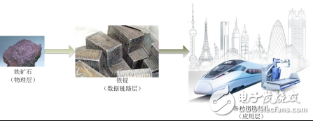
**Figure 2: From the physical layer to the application layer**
Because of this gap, industries that rely on CAN bus for automation often require a higher-level protocol to define how messages are used, including the interpretation of 11-bit or 29-bit identifiers and the 8-byte data fields. With the growing need for device interoperability, an open and standardized high-level protocol became essential. This led to the development of CANopen, which provides:
- **Application Layer**: Defines services and protocols that enable devices to communicate effectively within a network.
- **Communication Profile**: Specifies how devices are configured, what data they exchange, and how they communicate.
- **Device Profile**: Ensures that devices from different manufacturers behave consistently, enabling interoperability and interchangeability.
By adding these layers, CANopen fills the gap left by basic CAN and allows for more complex and standardized communication in industrial environments.