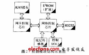
I. Introduction In the field of industrial automation, a large number of intelligent devices can be connected to the Internet through various channels, and information and data are transmitted to each other through the network, thereby realizing the functional autonomy of the intelligent field devices, the highly decentralized system structure, and the integration of supervision and control. . Fieldbus (FieldBus) is a new technology developed in response to this situation. The emergence of fieldbus marks the beginning of a new era in the field of industrial control technology. The development of this technology has greatly promoted the realization of device-oriented automation systems. Compared with the traditional Distributed Control System (DCS), he has the advantages of full openness, full dispersion, interoperability, etc., but it still has great limitations, mainly in the following aspects: 1. The current field instruments and equipment have low computing power and information processing capabilities, and complex control functions are still concentrated on one control computer, which cannot achieve full decentralized control, and there is a risk concentration phenomenon. 2. Fieldbus is only an integral part of the system, located at the bottom of the system, not enough to achieve a fully open architecture of the system. The system architecture is vertically combined, and there is a bottleneck in data communication. 3. The IEC61158 standard includes eight types of fieldbuses, which differ greatly from one another and cannot interoperate. There are certain difficulties in connecting to each other. 4. All controllers in the system operate independently, each performing independent data processing, which is difficult In order to achieve all information sharing, the system's real-time performance is not satisfactory. The above explanation shows that traditional classical PLC and fieldbus technology are not suitable for this requirement. Even technologies such as industrial PCs and OPCs can only be marginal improvements in the functionality of the system as long as they are embedded in a traditional system architecture. Therefore, in order to alleviate the heavy programming work and achieve the simplification of the system, it is necessary to change the structure of the system. With the continuous development of information technology, the field of industrial control will inevitably produce a unified, efficient and real-time control strategy that can compensate for fieldbus defects. Industrial Ethernet is a control technology that has rapidly developed to meet this need. Among all network technologies, Ethernet technology is the best choice so far, and he can meet all the following requirements: 1. Fully considering future development needs, with high transmission rate, currently reaching 100 Mb/s. 2. High transmission security and reliability, determinism of hub technology. 3. The application of the hub does not need to consider the expansion of the network. 4. A standard has been established: a new industrial bus standard. 5. Connected with IT, the application of "world standard" TCP/IP technology. 6. Random network access technology throughout the network. Ethernet is both a computer access to the local area network. Due to the significant increase in Ethernet transmission rate, the industrialization of physical layer standards and the formation of Ethernet hub technology, the emergence of Gigabit Ethernet technology and collision-free full-duplex fiber technology has enabled this advanced network technology to be advanced to earlier Industrial Ethernet technology is formed in an industrial control network that is considered unsuitable. Compared to current fieldbus-based control networks, industrial Ethernet-based control networks are a low-cost (many commercial Ethernet chipset and technology can be borrowed), high-performance control network solutions. Second, the program analysis (1) Design of embedded industrial Ethernet control system The control system network is divided into three layers: the information layer, the control layer, and the device layer (sensing/executing layer). Traditional control systems use Ethernet in the information layer, and different fieldbuses or other private networks are used in the control and device layers. Currently, almost all PLC and remote I/O vendors offer products that support TCP/IP Ethernet interfaces. With the Ethernet architecture, the controller's location can also break through the limitations of traditional network architectures, either on-site or in a central control room. At present, controllers and even remote I/Os support Ethernet functions more and more. Web servers have been integrated in some controllers and remote I/O modules, allowing users in the information layer to be directly as users of the control layer. Get the current state values ​​in the controller and remote I/O modules. In this solution, the network control system is divided into three parts: 1. Field device layer Includes embedded node control modules and field work machines. The former mainly completes the collection of on-site data, the processing and storage of front-end data, and communicates with the upper layer through the Internet interface. The control module implements server functions, and the information layer can be accessed via web browsing (supporting point-to-multipoint communication). The latter is mainly responsible for some auxiliary and monitoring affairs, such as on-site data transmission, historical data processing, and report output. 2. Internal information layer Mainly composed of internal Ethernet of the enterprise. Mainly complete the information collection and release of the entire system, that is, by accessing the Web server in the site node control module, the data of all the monitoring nodes under the monitoring are centralized in the LAN server through the HUB hub, and are uniformly managed and saved through the Web. The way to browse is published to the upper management department. 3. Internet network layer This layer connects the enterprise LANs through switches and routers, and completes the global release of information. The department located in the office can visually see the information of the work on the site, the completion of the production plan, and the working status of the equipment. Even if it is thousands of miles away, it can be used anytime, anywhere. Master the operation of the company (company), making telecommuting truly a reality. The industrial Ethernet control system solution is shown in Figure 1. (II) Implementation of embedded interface control module In the industrial Ethernet architecture, Ethernet is used as the system bus to connect the intelligent control module, and there is no difference between internal and external data communication. Hub technology is integrated into each controller to separate internal communications from external communications by allocating address space. The integration of hub technology and underlying protocols ensures the certainty, compatibility and integrity of Ethernet. At present, the protocols at the transport layer and the network layer are basically unified, and TCP/IP has become a standard network protocol, which is the "hub" for the normal operation of Ethernet. A key part of Industrial Ethernet technology is to implement a TCP/IP network communication protocol in a field-level node control module (such as a remote I/O module), that is, to establish a protocol stack. With the rapid development of electronics and information technology, it has become possible to embed the TCP/IP protocol into node modules by software or hardware. The software method embeds TCP/IP into the ROM of the microprocessor. The hardware method is to design the embedded processor and the ASIC device chip and directly use it as the network interface. The scheme adopts a RISC-based microcontroller with on-chip Flash program memory, which has system programming and debugging functions. Thanks to the CPU parallel pipeline mode and single clock cycle instructions, the instruction execution speed can reach 100 MI/s with 100 MHz crystal drive, and all I/O pins can be flexibly configured by programming. Based on the above features, the virtual peripheral (Virtual Peripheral) function can be realized: the CPU directly drives the common I/O port by executing the virtual software module to implement hardware peripheral functions (such as UART, I2C, SPI, CallerID, FSK, etc.). Most notably, this feature can be used to implement popular Internet protocol stacks such as HTTP, SMTP, POP3, TCP, UDP, ICMP, IP, and PPP. The implementation of the node module adopts a multi-tasking mode, and the single-chip microcomputer can also perform Internet protocol processing while performing data acquisition or completing I/O control tasks. In the application layer, you can choose any one of HTTP, SMTP, and POP3 as the communication protocol between the MCU system and the Internet remote management terminal; or develop other programs based on TCP and UDP protocols as application layer software. Using an Ethernet control chip, data packets can be sent to the Ethernet and connected to the Internet via Ethernet for true embedded TCP/IP devices. 2 is a schematic structural view of a control module.
Dc Gear Motor, namely Gear Reduction Motor, is based on ordinary Dc Motor , coupled with gear reduction gearbox.
The gear reducer is used to provide low speed and large torque.
At the same time, the gearbox with different deceleration ratio can provide different speed and torque.
Generally different industries, using different power dc motor, generally adopt custom parameter design pattern.
What are the four ratings of the Dc Gear Motor? The DC gear motor is often seen in our industrial production. Here Shunchang Motor gives you the knowledge of its four ratings. To talk about
precision instruments and meters,automobile industry, medical equipment, consumer electronics, household appliances, electric glass doors and Windows,etc., wide application range
Features: gear motor drive precision, small volume, large torque, low noise, durability, low energy consumption, customized power design,easy installation, easy maintenance;Simplify design and save space.
Method of use: the best stable in horizontal plane, installed on the dc gear motor output shaft parts, cannot use a hammer to knock,knock prone to press into the dc gear motor drive, may cause damage to internal components, and cannot be used in the case of blocked.
Operating temperature range:
Geared motors should be used at a temperature of -10~60℃.
The figures stated in the catalog specifications are based on use at ordinary room temperature catalog specifications re based on use at ordinary room temperature (approximately20~25℃.
If a geared motor is used outside the prescribed temperature range,the grease on the gearhead area will become unable to function normally and the motor will become unable to start.Depending on the temperature conditions ,it may be possible to deal with them by changing the grease of the motor's parts.Please feel free to consult with us about this.
Storage temperature range:
Geared motors should be stored ta a temperature of -15~65℃.
In case of storage outside this range,the grease on the gearhead area will become unable to function normally and the motor will become unable to start.
Service life:
â—Use with a load that exceeds the rated torque
â—Frequent starting
â—Momentary reversals of turning direction
â—Impact loads
â—Long-term continuous operation
â—Forced turning using the output shaft
â—Use in which the permitted overhang load or the permitted thrust load is exceeded
â—A pulse drive ,e.g.,a short break,counter electromotive force,PWM control
â—Use of a voltage that is nonstandard as regards the rated voltage
â—Use outside the prescribed temperature or relative-humidity range,or in a special environment.
â—Please consult with us about these or any other conditions of use that may apply,so that we can be sure that you select the most appropriate model.
when it come to volume production,we're a major player as well .each month,we rurn out 600000 units,all of which are compliant with the rohs directive.Have any questions or special needed, please contact us, we have the engineer group and best sales department to service to you Looking forward to your inquiry. Welcome to our factory.
Gear Motor Gear Motor,Micro Gear Motor,Small Gear Motor,Bike Lock Gear Motor Shenzhen Shunchang Motor Co., LTD. , https://www.scgearmotor.com
1. Rated Current: The rated current is the maximum current allowed to flow through the armature winding of the DC deceleration motor in accordance with the specified operating mode, in A.
2. Rated Voltage: The rated voltage is the maximum additional voltage that the armature winding of the motor can work safely, unit V. It
3. Rated Speed: Rated speed refers to the rotational speed of the Gear Reducer Motor in the rated voltage, rated current and output rated power under the circumstances of operation, the unit is r/min. Such
4, rated power: rated power refers to the motor in accordance with the specified mode of operation can provide output power. For motor, rated power is the output of mechanical power on the shaft.


