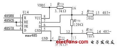
Since the 20-channel voltage measurement module supports RS485 serial communication, in order to realize the data communication between the single-chip microcomputer and the voltage measurement module, the RS485 communication interface must be designed. The host can transmit the query information to the slave through the RS485 interface, and the slave can respond to the collected real-time voltage data to the host. The RS485 signal transceiving chip MAX485 is used to realize the signal conversion. When designing the circuit, the level correspondence between the non-inverting terminal and the inverting terminal of the MAX485 chip should be fully considered. Since the slave responds to the initial bit-low level of the data frame to cause the host to receive the interrupt, only when the initial level of the non-inverting terminal A of the MAX485 chip is greater than the initial level of the inverting terminal B, the main controller can be guaranteed to open the receiving interrupt. There will be no accidental interruption, and the wrong data frame will be received. The schematic diagram of the RS485 interface circuit is shown in Figure 2. Figure 2 RS485 interface circuit schematic PCB Filter,PCB Mounting Filter,RFI Noise Filter,EMI Filter DC Power Jinan Filtemc Electronic Equipment Co., Ltd. , https://www.chinaemifilter.com