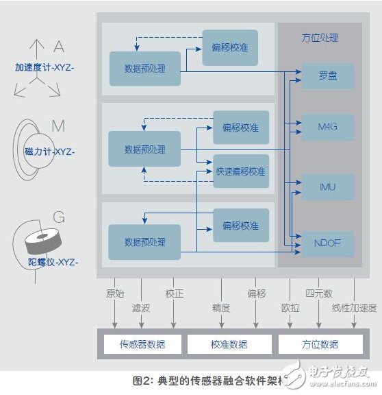
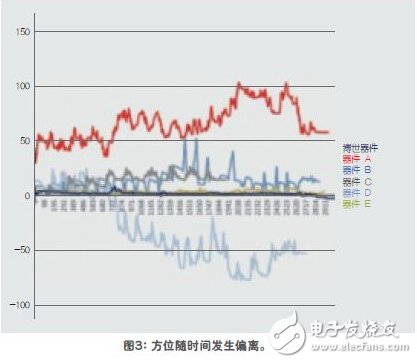
Sensor fusion is a highly specialized design area that requires proficiency in modeling and simulation techniques. It requires the best possible understanding of the sensor's working details and their shortcomings and interactions. Over the years, people's concerns have been brought into the fields of navigation, smartphone apps and games. But until now, with the accumulation and accumulation of a large amount of knowledge, people can get real and accurate results. In sensor-based fusion systems, operations require fine tuning. Nothing in the real world is as simple as "plug and play." The commissioning of a system requires that parameters be adjusted and that there is interaction between the operations of each sensor, so it can easily become a highly complex iterative process. Today's software has the ability to perform this "fine tuning" at a high level and provides OEMs with a simple and intuitive filter adjustment program (Figure 2). Pre-defined filters make fine adjustment faster Since fine-tuning of sensor fusion operations has evolved and simplified into filter tuning tasks, it provides developers with a valuable opportunity. By properly adjusting the filter, developers or OEMs can make the final product run in a market-differentiated manner. Because the balance of ownership management is automated, developers can make effective decisions, such as balancing trade-offs between highest stability and highest performance to fit the final target market. Key performance indicator measurement settings All sensor fusion techniques are not identical. There are significant differences between different vendors in terms of existing implementation techniques and testing. In order to get the right results, the correct software method with a proven, accurate library must be used. All hardware must be compatible and matched in terms of interface and timing parameters. A reasonable approach is to ensure the performance of the camera system, which will generate a position vector by moving the marker on the object according to the object (in this case, the smartphone). The orientation vector is then compared to the vector created by the sensor and recorded simultaneously with the data logging application. Using this camera-based system allows direct comparison of the final commercial device. Static accuracy Static accuracy is defined as the deviation between the measured device orientation and the actual device orientation when the device is placed in a stable position. In order to calculate the static accuracy, the mobile phone needs to collect the set data of heading, pitch and roll when it is placed at multiple positions. The static accuracy of a device is primarily influenced by the hardware parameters of the magnetometer and gyroscope and the weights assigned to them in the software. In devices with low static accuracy values, the end user can see large deviations in the absolute heading of the compass or map application, and when the device is in a static state, they can also see jitter in the interactive application (small rotation) mobile). This is due to software correction of gyroscope drift. It is more difficult to measure because of the rotational acceleration involved during the movement. Dynamic accuracy is calculated by collecting sets of data such as heading, pitch and roll when the phone is moving in different modes of motion (8-word dance, slow linear, fast and slow rotation, and game action). All data is collected at the fastest possible data rate. In devices with low dynamic accuracy, the end user can see a large deviation between the movement on the screen and the actual motion of the device. This is particularly noticeable in augmented reality applications because the movement of the enhancement unit is not synchronized with the real world. This is one of the reasons why users are dissatisfied after using virtual reality for a few minutes. Although the direct relationship is not obvious, the dynamic accuracy of large errors is also the main reason for the poor performance of indoor navigation applications. Since the user navigates between known fixed points (such as starting with a Wi-Fi or Bluetooth beacon), the sensor data can be used to calculate the trajectory. However, heading errors will accumulate over time, so devices with 15° poor dynamic accuracy can easily produce cumulative errors of more than 100° in 20s to 30s. Higher layer processing such as map matching may be able to make some corrections, but at the cost of greater power consumption (Figure 3). Calibration time Calibration time is defined as the time required to calibrate a magnetic sensor in a pure magnetic field environment from an uncalibrated state to a fully calibrated state. All magnetic sensors require calibration, but the method used for calibration defines whether the end user needs calibration and how to calibrate. Some devices use a 8-word dance calibration method that prompts the end user to calibrate the device by performing an 8-word motion in the air. Even with experienced testers, this method takes 5s to 6s to complete the device calibration. A device with a shorter calibration time uses a gyroscope to calibrate the magnetic sensor, which means that the calibration can be run in the background and the required device movement is much smaller. These movements are usually performed during normal operation, and the end user never has to actively calibrate the sensor. Bosch Sensor Technologies' Fast Magnetic Calibration (FMC) algorithm uses the latter method to ensure shorter calibration times. Azimuth stabilization time Azimuth stabilization time is defined as the time required to reach a precise, stable azimuth state after "after exercise." The azimuth stabilization time should be as short as possible so that the user does not see the delay between stopping the mobile device and stopping the device from moving to the correct position. This delay on the device is significant when the static and dynamic accuracy of the device is poor, as more time is required to correct the accumulated error in the movement. This effect is especially annoying in games and virtual/augmented reality applications that require real-time response. From a detailed assessment and analysis, it is clear that the sensor fusion described in this paper can now be widely used in professional and consumer markets. Field trials have shown that users can get valuable upgrades in performance and accuracy. While hardware and software concepts and engineering are complex, the task of transitioning from current sensor fusion to this advanced solution is relatively straightforward for developers. Sensor fusion technology has now evolved to a fairly mature stage. By integrating the sensor and sensor fusion building blocks into the same package, you can ensure that these units are optimized and work well together. System designers no longer need to spend time assembling, optimizing, and debugging traditional “always on†subsystems because each device is optimized for the highest accuracy and lowest power. This high level of technology and design creativity gives developers the advantage of providing great benefits to OEMs. Not only can they introduce highly differentiated products to the market, but they will also provide significant new generation of electronic devices to users. Improved performance and efficiency. Product categories of Storage Battery, we are specialized in manufacturers from China,Storage Battery Supplier suppliers/factory, wholesale high-quality products of manufacturing, we have the perfect after-sales service and technical support. Look forward to your cooperation! Storage Battery Solar Battery,Storage Battery,Solar Storage Battery,Solar Energe Storage Battery Changxing Deli Technology Co., Ltd. , https://www.delipowers.com